Difference between revisions of "RoboCupMechanical2008"
Jump to navigation
Jump to search
(→Index) |
|||
| (124 intermediate revisions by 7 users not shown) | |||
| Line 1: | Line 1: | ||
| − | + | This page houses the 2008 [[RoboCup]] Mechanical efforts. The 2007 efforts can be found [[RoboCupMechanical2007 | here]]. All development work will be done in Autodesk Inventor 2008. How to use Inventor and get it can be found on the [[How to Guide Inventor | Inventor How to Guide]]. Inventor is also available on our CAD Machines in Tin. | |
| − | This page | ||
| − | + | Mechanical team meets Tuesday 6-9pm with the general meeting at 7pm and 2-6pm on Sundays. More hours will be announced as deadlines approach. | |
| − | |||
| − | + | [[Image:RC2008DevRender.jpg|thumb|right|A developement rendering of a 2008 RoboCup robot]] | |
| − | == | + | ==Systems== |
| + | : [[RC08-Components|System Components and Bill of Materials]] | ||
| + | ===Drivetrain=== | ||
| + | : [[RC08Omni|Omni Wheels]] | ||
| + | : [[RoboCup Drive Motors/Gears|Motors/Gearing]] | ||
| + | : [[RC08Drive Module|Drive Module]] | ||
| + | ===Integration=== | ||
| + | : [[RC08Shell|Shell]] | ||
| + | : [[RC08Chassis|Chassis]] | ||
| + | ===Ball Control=== | ||
| + | : [[RC08-Dribbler|Dribbler]] | ||
| + | : [[RC08-Kicker|Kicker]] | ||
| + | : [[RC08-Chipper|Chipper]] | ||
| + | : [[RC08BallSens|Ball Sensor]] | ||
| + | ===Testing=== | ||
| + | : [[RC08METestRig|Test Rig]] | ||
| + | : Slope | ||
| + | : Impact Test | ||
| − | + | ==Schedule== | |
| − | + | * delivery of completed team of Robots 5/21/08 | |
| − | + | ==Specifications== | |
| − | 1) | + | * maximum robot weight - 1.8 kg |
| + | * ball speed after being kicked - 10 m/s | ||
| + | * dribbler bar speed - 8000 rpm | ||
| + | * compress time (time for dribbler to absorb ball's energy and compress) - .2 seconds | ||
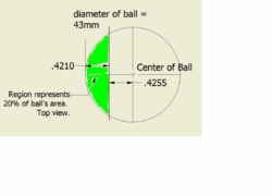
| + | * no more than 20% of the ball's area (seen from top view) may be occupied by the robot - a critical Robocup SSL Rule | ||
| + | ** see [[image:Ball sketch.PNG|250 px|Ball sketch]] | ||
| − | + | ==Meetings== | |
| − | |||
| − | + | ==Documentation== | |
| − | |||
| − | + | ==Testing== | |
| + | [[RoboCup Testing | RoboCup Testing]] | ||
| − | - | + | ==Quick Notes== |
| + | * field area 5 meters x 3.5 meters | ||
| + | * max ball speed - 10 m/s | ||
| + | * ball diameter - 43 mm | ||
| + | * ball mass - 46 grams | ||
| + | * 1 rpm = .105 rad/s | ||
| + | * ball material - DuPont Surlyn Ionomer [http://www2.dupont.com/Surlyn/en_US/ Dupont's Surlyn Page] | ||
| + | * coefficient of static friction of golf ball on felt carpet - .66 | ||
| + | ** last two points from Cornell 2003 Mechanical Documentation | ||
| − | + | ==Prototype Notes== | |
| − | + | *make drive module shaft out of stronger material to prevent bending | |
| + | *ground clearance needs to be increased to prevent the robot from rubbing on the carpet | ||
| + | *4mm holes on the dribbler assembly need to changed to .177" - clearance hole for a 8-32 screw - ease of assembly, prevent burring of the dribbler shafts | ||
| + | *binding of the drive modules can be reduced by adjusting the position of the motor, using the tolerance of its mounting screws | ||
| + | *design plastic guide block so hole for chipper hinge is centered | ||
| + | *dribbler motor plate needs to be wider and flush to the motor | ||
| + | *M2x4mm screws need to be ordered for the dribbler motor | ||
| + | *consider increasing diameter of dribbler roller to add strength to the piece | ||
| − | + | ==Useful Links== | |
| + | * [http://www.cis.cornell.edu/boom/2005/ProjectArchive/robocup/ Cornell Documents] (Look at 2003) | ||
| − | + | * [ftp://ftp.itam.mx/pub/alfredo/PAPERS/SotoWeitzenfeld80LARS2006.pdf Eagle Knights Dribbler Testing] | |
| − | + | *[http://www.sdp-si.com/D220/D220cat.htm#T35 Mechanical Engineering Tips] | |
| − | + | *[http://www.linuxcnc.org/handbook/gcode/g-code.html G-Code Tutorial] | |
| − | + | *[http://robojackets.org/~circuitben/ Overhead camera footage from Robocup 2007 Championship Match] | |
| − | + | *[http://www.drgears.com/gearterms/GearTermIndex.htm Dr. Gear - Gear Encyclopedia] | |
| − | + | *[http://shtylman.com/robocup_resource/mechanical/CornellRoboCupMechanicalDocumentation2004.doc Cornell 2004 Mechanical Documentation] | |
| − | 2) | + | *[http://pergatory.mit.edu/2.007/Resources/index.html#manufacturing MIT Design Handbook Index] (VERY GOOD) |
| − | + | *[http://thomasnet.com Global supplier and CAD drawing database] | |
| − | + | [[Category: RC Mechanical]] | |
| − | + | [[Category: 2007-2008]] | |
| − | |||
| − | |||
| − | |||
| − | |||
| − | |||
| − | |||
| − | |||
| − | |||
| − | |||
| − | |||
| − | |||
| − | |||
| − | |||
| − | |||
| − | |||
| − | |||
| − | |||
| − | |||
| − | |||
| − | |||
| − | |||
| − | |||
| − | |||
| − | |||
| − | |||
| − | |||
| − | |||
| − | |||
| − | |||
| − | |||
| − | |||
| − | |||
| − | |||
| − | |||
| − | |||
| − | |||
Latest revision as of 21:40, 24 May 2020
This page houses the 2008 RoboCup Mechanical efforts. The 2007 efforts can be found here. All development work will be done in Autodesk Inventor 2008. How to use Inventor and get it can be found on the Inventor How to Guide. Inventor is also available on our CAD Machines in Tin.
Mechanical team meets Tuesday 6-9pm with the general meeting at 7pm and 2-6pm on Sundays. More hours will be announced as deadlines approach.

Contents
Systems
Drivetrain
Integration
Ball Control
Testing
- Test Rig
- Slope
- Impact Test
Schedule
- delivery of completed team of Robots 5/21/08
Specifications
- maximum robot weight - 1.8 kg
- ball speed after being kicked - 10 m/s
- dribbler bar speed - 8000 rpm
- compress time (time for dribbler to absorb ball's energy and compress) - .2 seconds
- no more than 20% of the ball's area (seen from top view) may be occupied by the robot - a critical Robocup SSL Rule
- see
- see

Meetings
Documentation
Testing
Quick Notes
- field area 5 meters x 3.5 meters
- max ball speed - 10 m/s
- ball diameter - 43 mm
- ball mass - 46 grams
- 1 rpm = .105 rad/s
- ball material - DuPont Surlyn Ionomer Dupont's Surlyn Page
- coefficient of static friction of golf ball on felt carpet - .66
- last two points from Cornell 2003 Mechanical Documentation
Prototype Notes
- make drive module shaft out of stronger material to prevent bending
- ground clearance needs to be increased to prevent the robot from rubbing on the carpet
- 4mm holes on the dribbler assembly need to changed to .177" - clearance hole for a 8-32 screw - ease of assembly, prevent burring of the dribbler shafts
- binding of the drive modules can be reduced by adjusting the position of the motor, using the tolerance of its mounting screws
- design plastic guide block so hole for chipper hinge is centered
- dribbler motor plate needs to be wider and flush to the motor
- M2x4mm screws need to be ordered for the dribbler motor
- consider increasing diameter of dribbler roller to add strength to the piece
Useful Links
- Cornell Documents (Look at 2003)
- MIT Design Handbook Index (VERY GOOD)