Difference between revisions of "3lb Beginner's Guide"
(→Drum Spinner) |
m (Switched disadvantage columns for Aluminum 6061 and 7075. Also switched "HDPE aluminum" to "HDPE" for cost of HDPE plate.) |
||
| (35 intermediate revisions by 2 users not shown) | |||
| Line 14: | Line 14: | ||
=== Drum Spinner === | === Drum Spinner === | ||
| − | [[File:(Radiis).jpeg|right|thumb|320x180px|Radi and Radii | + | [[File:(Radiis).jpeg|right|thumb|320x180px|'''Drum Spinner - Radi and Radii''' Designed and built by RoboJackets Members (2016-2017)]] |
This weapon is a spinning solid cylindrical drum with teeth at the front of the robot. It is driven similarly to a vertical or horizontal spinner with a pulley system between the weapon and weapon motor. | This weapon is a spinning solid cylindrical drum with teeth at the front of the robot. It is driven similarly to a vertical or horizontal spinner with a pulley system between the weapon and weapon motor. | ||
| Line 30: | Line 30: | ||
* Large heavy weapon | * Large heavy weapon | ||
| − | '''Example Drum Spinners''' | + | '''Example Drum Spinners designed and built by RoboJackets''' |
* [[Radii]] - 3rd place winner at Motorama 2017 | * [[Radii]] - 3rd place winner at Motorama 2017 | ||
* [[Snuti]] - Competed at Motorama 2017 and Sparkfun 2017 | * [[Snuti]] - Competed at Motorama 2017 and Sparkfun 2017 | ||
| Line 36: | Line 36: | ||
=== Horizontal Spinner === | === Horizontal Spinner === | ||
| − | [[File:chewi.jpg|thumb|320x240px| | + | [[File:chewi.jpg|thumb|320x240px|'''Horizontal Bar Spinner - Chewi''' Designed and built by RoboJackets Members (2017-2018)]] |
The weapon is a flat spinning bar or disk at the front of the robot. It is also driven similarly to a drum or vertical spinner with a pulley system between the weapon and weapon motor. | The weapon is a flat spinning bar or disk at the front of the robot. It is also driven similarly to a drum or vertical spinner with a pulley system between the weapon and weapon motor. | ||
'''Pros''' | '''Pros''' | ||
| − | * High | + | * High damage output |
* Large strike zone | * Large strike zone | ||
* Easy to design so it can drive while flipped | * Easy to design so it can drive while flipped | ||
| Line 51: | Line 51: | ||
* Needs a lot of structural support on the weapon to prevent damage from recoil | * Needs a lot of structural support on the weapon to prevent damage from recoil | ||
| − | '''Example Horizontal Spinners''' | + | '''Example Horizontal Spinners designed and built by RoboJackets''' |
* [[Ki]] - Competed at Sparkfun 2016 and Motorama 2017 | * [[Ki]] - Competed at Sparkfun 2016 and Motorama 2017 | ||
* [[Chewi]] - Competed at Motorama 2018, RoboGames 2018, and Sparkfun 2018 | * [[Chewi]] - Competed at Motorama 2018, RoboGames 2018, and Sparkfun 2018 | ||
| + | * [[Daddi]] - Competed at Motorama 2019 | ||
=== Vertical Spinner === | === Vertical Spinner === | ||
| − | [[File:Golden Esci.jpeg|thumb|Vertical Bar Spinner]] | + | [[File:Golden Esci.jpeg|thumb|'''Vertical Bar Spinner - Esci''' Designed and built by RoboJackets Members (2017-2018)]] |
A robot with a vertically spinning weapon at the front of the robot. Typically this weapon is complemented by a surrounding wedge to lift opponents into the weapon. It is also driven similarly to a drum or horizontal spinner with a pulley system between the weapon and weapon motor. | A robot with a vertically spinning weapon at the front of the robot. Typically this weapon is complemented by a surrounding wedge to lift opponents into the weapon. It is also driven similarly to a drum or horizontal spinner with a pulley system between the weapon and weapon motor. | ||
| Line 63: | Line 64: | ||
'''Pros''' | '''Pros''' | ||
* Great damage output | * Great damage output | ||
| − | * Allows for the use of a wedge, which acts | + | * Allows for the use of a wedge, which acts as armor and directs bots into the weapon |
* If the weapon breaks, it still functions as a wedge bot | * If the weapon breaks, it still functions as a wedge bot | ||
| Line 71: | Line 72: | ||
* Weapon has to be smaller to maintain a low center of gravity (keep the bot short) | * Weapon has to be smaller to maintain a low center of gravity (keep the bot short) | ||
| − | '''Example Vertical Spinner''' | + | '''Example Vertical Spinner designed and built by RoboJackets''' |
| − | * [[Esci]] | + | * [[Esci]] - Competed in Motorama 2018 and RoboGames 2018 |
=== Ring Spinner === | === Ring Spinner === | ||
| − | [[File: | + | [[File:Smitti.png|thumb|240x240px|'''Ring Spinner - Smitti''' Designed and built by RoboJackets Members (2014-2015)]] |
| − | This weapon is a spinning ring with teeth that surround the entire frame. Generally, the ring is supported by "rollers" which have bearings to reduce friction and support the ring with a male-female interface. The ring is typically driven directly by the weapon motor which has a casing of a high friction material such as rubber. | + | This weapon is a spinning ring with teeth that surround the entire frame. Generally, the ring is supported by "rollers", which have bearings to reduce friction and support the ring with a male-female interface. The ring is typically driven directly by the weapon motor, which has a casing of a high friction material such as rubber. |
| − | Additionally, there is a variant of the Ring Spinner called the Shell Spinner. The Shell Spinner is nearly identical to the Ring Spinner, except instead of a "ring" that is spun around, the entire robot is covered in a shell which is spun. This allows for even more weapon coverage, at the cost of more weight being required for the larger shell, as well as the need for a stronger motor to spin it. | + | Additionally, there is a variant of the Ring Spinner called the Shell Spinner. The Shell Spinner is nearly identical to the Ring Spinner, except instead of a "ring" that is spun around, the entire robot is covered in a shell, which is spun. This allows for even more weapon coverage, at the cost of more weight being required for the larger shell, as well as the need for a stronger motor to spin it. |
'''Pros''' | '''Pros''' | ||
| Line 92: | Line 93: | ||
* Can be difficult to drive | * Can be difficult to drive | ||
| − | '''Example Ring Spinners''' | + | '''Example Ring Spinners designed and built by RoboJackets''' |
| − | * [[Qti]] | + | * [[Qti]] - Competed in Motorama 2017 |
| − | * [[Smitti Werbenjagermanjensen]] | + | * [[Smitti Werbenjagermanjensen]] - Competed in Motorama 2015 |
=== Wedge === | === Wedge === | ||
| Line 101: | Line 102: | ||
The weapon is the bot itself with the main structure forming a wedge with the intent on trying to flip over, or lift the enemy bot off the ground. | The weapon is the bot itself with the main structure forming a wedge with the intent on trying to flip over, or lift the enemy bot off the ground. | ||
| + | |||
| + | Members of the RoboJackets Battlebot team do not build Wedge's because there is no real design challenge in designing a Wedge, and RoboJackets values the educational experience of designing a more complex robot. Building a more complex robot allows you to learn engineering skills that scale to more advanced competitions. Ultimately, while Wedge bots may be good at winning competitions winning the competition isn't the goal. The true goal is to learn about the design process and have fun! | ||
'''Pros''' | '''Pros''' | ||
| Line 110: | Line 113: | ||
* Doesn't challenge your engineering abilities as much as a bot with a traditional weapon. | * Doesn't challenge your engineering abilities as much as a bot with a traditional weapon. | ||
* No true destructive power which means if the enemy cannot be flipped or lifted, winning will be very difficult. | * No true destructive power which means if the enemy cannot be flipped or lifted, winning will be very difficult. | ||
| − | |||
| − | |||
== Design Process == | == Design Process == | ||
| Line 117: | Line 118: | ||
=== Introduction === | === Introduction === | ||
| − | The following is a detailed explanation of the design process for the RoboJackets BattleBots team. While this is specific to our team, it can be used as a general guide for | + | Now that you have selected a robot type, you're ready to start designing and building! The following is a detailed explanation of the design process for the RoboJackets BattleBots team. While this is specific to our team, it can be used as a general guide for any team that wants to improve their design process. |
| − | Being successful in competitions starts with the design process. While everyone wants to immediately jump into machining and get their bot done, without a proper design process the end result will be ineffective and probably nonfunctional. Additionally, without a proper CAD assembly with accompanying dimensions machining will not result in usable parts. So while it might not be as exciting as machining and assembling, it | + | Being successful in competitions starts with the design process. While everyone wants to immediately jump into machining and get their bot done, without a proper design process the end result will be ineffective and probably nonfunctional. Additionally, without a proper CAD assembly with accompanying dimensions machining will not result in usable parts. So while it might not be as exciting as machining and assembling, it pay off in the end. Spending extra time on the design process will highly increase the quality of your final design and assembly. |
| − | + | [[File:Diagram2.jpeg|800x487px]] | |
=== Step 0: Brainstorming === | === Step 0: Brainstorming === | ||
| Line 127: | Line 128: | ||
[[File:Senpai_Brainstorm.jpg|thumb|upright=0.65|Example Brainstorm Sketches]] | [[File:Senpai_Brainstorm.jpg|thumb|upright=0.65|Example Brainstorm Sketches]] | ||
| − | The design process begins unofficially with brainstorming. Once you have an idea about what type of bot you want to build | + | The design process begins unofficially with brainstorming. Once you have an idea about what type of bot you want to build |
| + | * Research notable examples of that type of bot. | ||
| + | * Look for examples with different types of weapons, armor, and drive systems. | ||
| + | * Try to find some videos of these bots actually competing. | ||
| + | * See what works and what doesn't about different designs. | ||
| − | + | Once you've seen enough through researching different robots... | |
| + | * Start piecing together your ideas into complete concepts once you've seen enough. | ||
| + | * Do a rough sketch of the shape of the chassis, weapon, etc. | ||
| + | * If there are some unique features on your concept, write out some notes so that when you or your team revisit it, it will be more easy to understand. | ||
| − | + | Don't limit yourself to just one idea either, the more ideas you bring to your team during the first few meetings when you decide on an overall design, the better. It is worth mentioning that you will be on a team, so don't get TOO attached to one idea, as not one person on the team will end up having designed the entire bot. | |
| + | |||
| + | On the right, you can see an example of what good brainstorm sketches look like. There are many ideas drawn out, with a variety of features demonstrated between them. Things to focus your brainstorming on would include... | ||
| + | * Weapon type | ||
| + | * Weapon shape | ||
| + | * Drive system | ||
| + | * Overall shape | ||
| + | * Armor | ||
| + | |||
| + | It's important to note that no idea is a bad idea during the brainstorming phase. Any and all ideas are beneficial. While a given idea may not work, when you gather with your team you may find that a teammate will have an idea that could take a not so good design and make it great. Additionally, you may find that your team will go back to these brainstorming ideas for inspiration to solve issues with the design way down the line. In other words, the more ideas you come up with and put down on paper, the better! | ||
=== Step 1: Sketch === | === Step 1: Sketch === | ||
| Line 138: | Line 155: | ||
[[File:Senpai_Final_Sketch.png|thumb|upright=0.5|Example Final Sketch]] | [[File:Senpai_Final_Sketch.png|thumb|upright=0.5|Example Final Sketch]] | ||
| − | This is when the design process will start properly. Once you're on a team the first goal is to come up with a bot design. Think broad. Focus on features. | + | This is when the design process will start properly. Once you're on a team, the first goal is to come up with a bot design. Think broad. Focus on features. The design process is iterative, so you will make changes to this design. However, this doesn't mean that it's not worthwhile to come up with some rudimentary overall dimensions, such as the overall length, width, and height of the bot. These dimensions can be based loosely off of previous bots as a guideline. |
On the right, there are two examples of sketches that would be created during this stage in the design process. | On the right, there are two examples of sketches that would be created during this stage in the design process. | ||
| − | The top sketch is a good example of what should be drawn at the start of the sketching step. As a team, you will produce several of these sketches, each time adding more details as you discuss the design. As you can see this top view shows the approximate location of the frame, wheels, motors, and weapon. Details such as fasteners and electronics are not yet included, as this sketch would be developed before those are considered. It is important to work out details in a logical order. Start with a sketch similar to those in the brainstorming phase | + | The top sketch is a good example of what should be drawn at the start of the sketching step. As a team, you will produce several of these sketches, each time adding more details as you discuss the design. As you can see this top view shows the approximate location of the frame, wheels, motors, and weapon. Details such as fasteners and electronics are not yet included, as this sketch would be developed before those are considered. It is important to work out details in a logical order. |
| + | # Start with a sketch similar to those in the brainstorming phase and work out how the structure would work. | ||
| + | # Add in larger important things like the weapon and armor. | ||
| + | # Add in smaller important things like the motors, wheels, and belts. | ||
| + | # Add in the fine details like wires, electronics, and fasteners. | ||
| + | |||
| + | This process will allow you to logically work through taking a concept in your mind and putting it onto paper. | ||
| − | As | + | As more details are finalized, the sketches will become increasingly complex. Eventually, your team should have a detailed final sketch, such as the bottom example. As you can see, most if not all components are included. Multiple views are included as well, which will significantly help with visualization of the final design. It's noteworthy to see that while the sketch is incredibly detailed (and no you don't need to be an artist, most final sketches won't look this good), it still wouldn't be enough to jump directly into CAD. That's why we have the next step! |
=== Step 2: Draw === | === Step 2: Draw === | ||
| Line 151: | Line 174: | ||
[[File:Senpai_Individual_Part.jpg|thumb|upright=0.5|Example Part Drawing]] | [[File:Senpai_Individual_Part.jpg|thumb|upright=0.5|Example Part Drawing]] | ||
| − | Once you've got an overall sketch of the bot, its time to start drawing some individual parts out and assign them some dimensions. This is important, as having some predetermined dimensions will make the CAD process easier. Make sure that your team is communicating during this process, as its important that everyone understands the dimensions so that any given member could make the CAD part for any given part. The more your team understands the dimensions you define, the faster and more efficient the CAD process will be. Additionally, drawings should be made that give | + | Once you've got an overall sketch of the bot, its time to start drawing some individual parts out and assign them some dimensions. This is important, as having some predetermined dimensions will make the CAD process easier. Make sure that your team is communicating during this process, as its important that everyone understands the dimensions so that any given member could make the CAD part for any given part. The more your team understands the dimensions you define, the faster and more efficient the CAD process will be. Additionally, drawings should be made that give explicit details in areas of the bot that have complex assemblies and sections of the bot. Having these draw out ahead of time will expedite the process of translating the drawing into a CAD assembly. |
| − | + | You will also have to determine what material the parts are made out of. See the Commonly used materials section for more details | |
| − | Another thing to consider during this time | + | Another thing to consider during this time is how you will attach the parts into a complete assembly. Consider using a puzzle-fit, the number of screws used to connect two parts, location of holes, and size and type of screws. Beware intersections of screws, and don't have so many screws that your part is completely filled with holes, or "Swiss-cheesed". |
The top right image shows a detailed drawing which provides details about the materials and assembly of a given joint. Without this drawing, just using the final sketch, it would have been much harder to translate this isn't CAD. | The top right image shows a detailed drawing which provides details about the materials and assembly of a given joint. Without this drawing, just using the final sketch, it would have been much harder to translate this isn't CAD. | ||
| Line 161: | Line 184: | ||
The middle right image shows a detailed drawing for the assembly of the motor and the motor mount. Once again, the added details would make it much easier for the creation of the part in CAD. | The middle right image shows a detailed drawing for the assembly of the motor and the motor mount. Once again, the added details would make it much easier for the creation of the part in CAD. | ||
| − | This step can be done simultaneously with | + | This step can be done simultaneously with Steps 3 and 4, as you draw and dimension parts as you need them during the early meetings. However, it's important not to put off finishing the drawings for all parts, as it can make it harder to work outside of meetings. There should always be a group present when dimensioning parts, so if you don't have any parts that are dimensioned, you can't make a good CAD part. |
=== Step 3: Picking a motor === | === Step 3: Picking a motor === | ||
| − | + | When picking a motor, there are 3 things to consider. The motor properties (things specific to the motor you '''cannot''' control), the design properties (things specific to your design you '''can''' control), and the desired specifications (specifciations that you want in the end). | |
| − | + | Motor properties you cannot control: | |
| − | * KV (RPM/V): This will be used alongside our voltage value to find the Rotations Per Minute (RPM) of the motor. | + | * '''KV (RPM/V)''': This will be used alongside our voltage value to find the Rotations Per Minute (RPM) of the motor. |
| − | * Power (W): This will be used alongside our calculated RPM value to find the Force and Spin-up time for the weapon. This value is typically between 500-800W. | + | * '''Power (W)''': This will be used alongside our calculated RPM value to find the Force and Spin-up time for the weapon. This value is typically between 500-800W. |
| − | * Max Current (A): This is an important number to know, as it will affect which ESC you need. The greater the max current, the bigger and heavier ESC you will need, so aim for a low max current. | + | * '''Max Current (A)''': This is an important number to know, as it will affect which ESC you need. The greater the max current, the bigger and heavier ESC you will need, so aim for a low max current. |
| − | * Max Voltage (V): This will be used alongside our KV value to find the RPM of the motor | + | * '''Max Voltage (V)''': This will be used alongside our KV value to find the RPM of the motor |
| − | * Dimensions: The size of the motor is also an important factor to keep in mind, as a large motor could force you to build a larger bot to house it. A larger bot will end up needing thinner, smaller, and weaker walls to keep the weight below 3 lbs. | + | * '''Dimensions''': The size of the motor is also an important factor to keep in mind, as a large motor could force you to build a larger bot to house it. A larger bot will end up needing thinner, smaller, and weaker walls to keep the weight below 3 lbs. |
| − | * Weight: Obviously the weight of the motor matters, as a heavy motor will make it harder to build a sturdy bot due to the use of less heavy but weaker walls. | + | * '''Weight''': Obviously the weight of the motor matters, as a heavy motor will make it harder to build a sturdy bot due to the use of less heavy but weaker walls. |
Please note that some websites have a bad habit of listing the dimensions and weight of the box the motor comes in, rather than the motor itself. | Please note that some websites have a bad habit of listing the dimensions and weight of the box the motor comes in, rather than the motor itself. | ||
| Line 178: | Line 201: | ||
Also, be aware that many of the values provided by websites are the theoretical maximums, and won't be what you actually observe. However, for the sake of these calculations, you can just use these values. | Also, be aware that many of the values provided by websites are the theoretical maximums, and won't be what you actually observe. However, for the sake of these calculations, you can just use these values. | ||
| − | + | Design properties you can control: | |
| − | * Gear ratio: The gear ratio is the ratio of the diameter of the motor to the diameter of whatever you are rotating, like a pulley or the weapon drum. This will be an important factor, as it will determine the RPM of the weapon. | + | * '''Gear ratio''': The gear ratio is the ratio of the diameter of the motor to the diameter of whatever you are rotating, like a pulley or the weapon drum. This will be an important factor, as it will determine the RPM of the weapon. |
| − | * Mass Moment of Inertia (J): This will be used in your calculations for Force and Spin-up time, and it can be found by making the weapon in Inventor, then checking its physical properties. | + | * '''Mass Moment of Inertia (J)''': This will be used in your calculations for Force and Spin-up time, and it can be found by making the weapon in Inventor, then checking its physical properties. |
| − | + | End Specifications that you desire: | |
| − | * Weapon RPM: This will be an important factor for your over destructive capability. For smaller spinning weapons, such as a drum, RPMs greater than 8000RPM are desirable. For larger spinning weapons, such as a bar, RPMs between the range of 2000-5000RPM are desirable. This number is lower than the smaller weapons because if you RPM is too high with a bar spinner, you risk significant recoil when you hit the enemy and severe gyroscopic effects inhibiting responsive driving. Its one thing to rip the opponent's bot in half, but if you destroy your own bot in the process it's meaningless. | + | * '''Weapon RPM''': This will be an important factor for your over destructive capability. For smaller spinning weapons, such as a drum, RPMs greater than 8000RPM are desirable. For larger spinning weapons, such as a bar, RPMs between the range of 2000-5000RPM are desirable. This number is lower than the smaller weapons because if you RPM is too high with a bar spinner, you risk significant recoil when you hit the enemy and severe gyroscopic effects inhibiting responsive driving. Its one thing to rip the opponent's bot in half, but if you destroy your own bot in the process it's meaningless. |
| − | * Spin-up time (s): This value represents the amount of time required to get the weapon from rest to its max RPM. The first to strike in the competition will often gain the immediate upper hand and if the enemy bot runs into your weapon before its spun-up completely, you will deal little to no damage and the weapon will once again need to spin-up from rest again. Keeping this value as low as possible is incredibly important. In general, a Spin-up time of around 1 second would be reasonable, but ultimately it's up to your team to make the call on what you think is an acceptable amount of time. | + | * '''Spin-up time (s)''': This value represents the amount of time required to get the weapon from rest to its max RPM. The first to strike in the competition will often gain the immediate upper hand and if the enemy bot runs into your weapon before its spun-up completely, you will deal little to no damage and the weapon will once again need to spin-up from rest again. Keeping this value as low as possible is incredibly important. In general, a Spin-up time of around 1 second would be reasonable, but ultimately it's up to your team to make the call on what you think is an acceptable amount of time. |
| − | * Kinetic Energy (J): This value represents the actual energy that your spinning weapon will produce, and therefore transfer into the other robot. | + | * '''Kinetic Energy (J)''': This value represents the actual energy that your spinning weapon will produce, and therefore transfer into the other robot. |
As part of getting these values, you will have to calculate several more values. The process by which you calculate these values and the ones mentioned in this section can be found below in the Calculations section of this guide. | As part of getting these values, you will have to calculate several more values. The process by which you calculate these values and the ones mentioned in this section can be found below in the Calculations section of this guide. | ||
| Line 193: | Line 216: | ||
=== Step 4: CAD Parts === | === Step 4: CAD Parts === | ||
| − | + | This step will actually start at the same time as you're looking at choosing a motor. As part of your calculations, you will need the weapon to made in Inventor so that you can get its Mass Moment of Inertia. From there you will need to create a part for the motor that your team ends up choosing, using the dimensions and weight provided by the website you found the motor on. | |
| − | |||
| − | |||
| − | |||
| − | |||
| − | |||
| − | |||
| − | + | Remember that the parts will need to be manufactured from stock, so once you have determined a way to manufacture a part, check how much the stock you'd need will cost and how much material will be wasted as part of your manufacturing. For example, if you have a part that you know how you could manufacture, but it would require a $100 chunk of aluminum, most of which is removed in the process, maybe look at redesigning the part to be simpler so it can be manufactured with cheaper stock. | |
| + | Here are some tips for making combat robot parts in CAD... | ||
| − | + | * ''' Assign dimensions ''' in a way that makes it easy to go back and change the values later. This is often accomplished by avoiding making dimensions all dependent on each other, and instead of keeping them based off of the part's overall dimensions. | |
| + | * ''' Utilize any standardized CAD''' parts for things like electronics that may be provided either online or by a mentor. This will save you the time that would be spent making the part yourself. | ||
| + | * '''Assign the material property of a part''', to ensure that it's reported weight is correct. The default "generic" material will not accurately report your weight, which will result in you being overweight once everything is built. You also may find that you have only made half of the parts you need, and the overall weight is already too high. With this information, you can go ahead and adjust the dimensions of the parts you've already made to reduce the weight. | ||
| + | * '''Begin working on your assembly''' earlier rather than later! You don't need to actually have every single part in CAD before you start putting parts into an assembly. See the next step for more information! | ||
| − | + | Proper CADing is a team effort, not a solo endeavor. When you work alone, you risk misinterpreting a dimension or drawing. During meetings, one or two people should be actively working on the CAD with the remaining members talking through the process with them. Communication is key! You will end up creating quality uniform parts only by working together. Taking turns working on parts is also important, to ensure everyone gets time working with Inventor. Please remember that it is expected that your team will meet and work outside of our regularly scheduled meetings! | |
| − | |||
| − | |||
=== Step 5: CAD Assembly === | === Step 5: CAD Assembly === | ||
| − | Once | + | Once the parts are made, its time to start putting together an assembly. You'll need to completely finish the assembly before you can undergo a design review. There are several "Do's and Dont's" to consider with the assembly... |
| + | * '''Do''' focus on making sure the overall weight is below 3lbs. It's important to have an assembly that is not only below 3 lbs but is safely below 3 lbs. | ||
| + | * '''Do''' account for the weight of things potentially not present in the assembly, such as wires, connectors, and material imperfections. | ||
| + | * '''Do''' add in the fine details like screws and clearances between parts to account for inaccuracies when cutting out parts. | ||
| + | * '''Do''' create sub-assemblies, which will allow your team to work on multiple aspects of the robot simultaneously. | ||
| + | * '''Don't''' assume that something can be left out of the final assembly. The assembly should include every feasible component as the real thing. | ||
| + | * '''Don't''' assign random colors and textures to parts. This will make it harder for people to understand the intended materials from appearance alone. | ||
| + | * '''Don't''' underestimate the amount of work required to put everything into an assembly. Oftentimes new issues will present themselves after putting everything together. | ||
| + | * '''Don't''' make all changes in the same assembly. Save copies of your assembly along the way, so you can reference the old versions if need be. | ||
| − | + | During this time, it is also important to begin working on a Bill of Materials, or BOM for short. This BOM will be a master list of the materials required to create the robot, and where they can be purchased. While there is no specific format for a BOM, the following are expected to be included in one... | |
| − | + | * Dimension of stock plates/sheets required to manufacture parts. | |
| − | During this time, it is also important to begin working on a Bill of Materials, or BOM for short. This BOM will be a master list of the materials required to create the robot, and where they can be purchased. Keeping an accurate and through BOM will allow you to launch directly into manufacturing as fast as possible after the design is complete. | + | * Quantity of non-stock materials such as screws, bearings, and belts. |
| + | * Sources for where the materials can be purchased. | ||
| + | * Any necessary notes related to the parts and materials needed. | ||
| + | Keeping an accurate and through BOM will allow you to launch directly into manufacturing as fast as possible after the design is complete. | ||
=== Step 6: Design Review === | === Step 6: Design Review === | ||
| Line 221: | Line 251: | ||
The whole design process is leading up to one thing: The Design Review. During the design review, you will present your team's assembly to the rest of the BattleBots team. Both your peers and the senior members will ask you questions about your design and point out design flaws and recommendations on how to address them. Often times your first design review will be fairly harsh, with senior members finding plenty of issues with your design. While this may seem mean-spirited, they are simply trying to help you build the best bot that you can. The larger bots will often undergo the design review 3-5 times before they are finally approved to start machining, so even the senior members have to go through this process. Because the 3 lb bots are much simpler, usually only 2 design reviews will be needed. | The whole design process is leading up to one thing: The Design Review. During the design review, you will present your team's assembly to the rest of the BattleBots team. Both your peers and the senior members will ask you questions about your design and point out design flaws and recommendations on how to address them. Often times your first design review will be fairly harsh, with senior members finding plenty of issues with your design. While this may seem mean-spirited, they are simply trying to help you build the best bot that you can. The larger bots will often undergo the design review 3-5 times before they are finally approved to start machining, so even the senior members have to go through this process. Because the 3 lb bots are much simpler, usually only 2 design reviews will be needed. | ||
| − | It's important to take notes during the design review, as even a "good" design review will result in enough changes that you'll need to write them all down. | + | '''It's important to take notes during the design review, as even a "good" design review will result in enough changes that you'll need to write them all down. You will likely get a lot of feedback, and while in the moment you may feel like you'll remember it all it will be impossible to remember every little comment.''' |
=== Step 7: Revise and repeat === | === Step 7: Revise and repeat === | ||
| − | Once you get out of a design review, it's important to strike fast while the iron is hot. After your first design review, there will more than likely be several huge changes that you'll need to make to both your individual parts and the assembly as a whole. There is NOT a lot of time between the first and second design reviews, due to the natural time constraints of the | + | Once you get out of a design review, it's important to strike fast while the iron is hot. After your first design review, there will more than likely be several huge changes that you'll need to make to both your individual parts and the assembly as a whole. There is NOT a lot of time between the first and second design reviews (often only a week or two), due to the natural time constraints of the 3lb program. So it's important to start working on these changes sooner rather than later. It's important to also make sure you address ALL the things that are mentioned during the review, as it's important not the waste everyone's time with repeat issues from the previous review. |
=== Step 8: BUILD! === | === Step 8: BUILD! === | ||
| − | Now | + | Now finally you can begin manufacturing! Keep in mind... |
| + | * You will need to make minor adjustments to the design as you manufacture, and when you do so make sure to update your CAD to reflect these changes. | ||
| + | * Beware changing too much and causing the overall assembly to be overweight. | ||
== Calculations == | == Calculations == | ||
| − | Below is a step | + | Below is a step by step guide on the calculations required to determine what motor to choose for your bot. Keep in mind these calculations are fairly simplistic and don't take several real-world factors into account. Additionally, these values will be computed based off of what is reported by the manufacturers, which are often "best case scenario" and are not what you should expect to see in practice. |
=== Step 1: Get values for the motor === | === Step 1: Get values for the motor === | ||
| Line 250: | Line 282: | ||
=== Step 3: Determine intermediary values === | === Step 3: Determine intermediary values === | ||
| − | + | In order to calculate our desired values, we need to calculate some intermediary values to use in our later calculations. | |
* '''ω''': Angular Velocity (rad/s) | * '''ω''': Angular Velocity (rad/s) | ||
* '''RPM''': Rotations Per Minute | * '''RPM''': Rotations Per Minute | ||
| Line 265: | Line 297: | ||
'''τ<sub>output</sub> = τ<sub>input</sub> / e''' | '''τ<sub>output</sub> = τ<sub>input</sub> / e''' | ||
| − | For the calculations past this point, please use | + | For the calculations past this point, please use these new "output" versions of ω and τ in place of our old values. |
=== Step 5: Get our desired values === | === Step 5: Get our desired values === | ||
| − | Finally, we are | + | Finally, we are ready to calculate the final values that we actually want! |
* '''KE''': Kinetic Energy | * '''KE''': Kinetic Energy | ||
* '''t''': Spin-up Time (s) | * '''t''': Spin-up Time (s) | ||
| Line 312: | Line 344: | ||
= Commonly Used Materials = | = Commonly Used Materials = | ||
| − | In this section, I will describe some of the most common materials used to build a 3lb combat robot. | + | In this section, I will describe some of the most common materials used to build a 3lb combat robot. Aluminum, Steel, and Plastic are the most commonly used materials for building a 3lb robot. While there are a few more materials that some teams use (e.g. carbon fiber or titanium), these three materials are affordable, lightweight enough to be used in a 3lb combat robot, common enough that they can be easily purchased from a variety of sources, and strong enough to be used in for combat. |
== Aluminum == | == Aluminum == | ||
| + | |||
| + | '''Common Uses''' | ||
| + | * Majority of structural pieces | ||
| + | * Any non-striking surface that needs to be strong | ||
| + | * Drum for drum spinners | ||
'''Features''' | '''Features''' | ||
| Line 321: | Line 358: | ||
* Good all-purpose material | * Good all-purpose material | ||
| − | + | Aluminum is one of the most commonly used materials for building a combat robot. This is because it is lightweight but strong enough to be used for the core structure of the robot. | |
| − | |||
| − | |||
| − | |||
| − | + | The most commonly used aluminum alloys are 6061 and 7075. Below are some of the advantages and disadvantages between these two alloys, | |
| + | {| class="wikitable" | ||
| + | |- | ||
| + | ! scope="col"| | ||
| + | ! scope="col"| 6061 Aluminum | ||
| + | ! scope="col"| 7075 Aluminum | ||
| + | |- | ||
| + | ! scope="row"| Advantages | ||
| + | | | ||
| + | * Significantly cheaper | ||
| + | * Easier to machine | ||
| + | | | ||
| + | * Significantly stronger | ||
| + | * Resists deformation | ||
| + | |- | ||
| + | ! scope="row"| Disadvantages | ||
| + | | | ||
| + | * Much weaker | ||
| + | * Doesn't resist deformation | ||
| + | | | ||
| + | * Significantly more expensive | ||
| + | * Much harder to machine | ||
| + | |} | ||
| − | + | RoboJackets typically sources its aluminum from [https://www.midweststeelsupply.com/store/ Midwest Steel Supply] and [https://www.mcmaster.com/ McMaster-Carr]. A 12" x 12" x 0.25" plate of 6061 aluminum costs approximately $22. | |
== Steel == | == Steel == | ||
| − | |||
| − | |||
| − | |||
| − | |||
| − | |||
'''Common Uses''' | '''Common Uses''' | ||
| Line 343: | Line 394: | ||
* Any striking surfaces | * Any striking surfaces | ||
| − | + | '''Features''' | |
| + | * Very strong | ||
| + | * Very heavy | ||
| + | * Great for resisting deformation | ||
| − | The most | + | Because of its heavyweight, steel should be used sparingly, and it is typically reserved for the part that strikes the enemy robot. This is to ensure that all of the energy of the collision is transferred into the enemy bot, and not into deforming your weapon. Additionally, steel is often utilized as the striking surface on the weapon. |
| + | |||
| + | The most common type of steel used is low-carbon steel as it is easy to machine, strong, and fairly cheap. | ||
| + | |||
| + | RoboJackets typically sources its steel from [https://www.midweststeelsupply.com/store/ Midwest Steel Supply] and [https://www.mcmaster.com/ McMaster-Carr]. A 12" x 12" x 0.25" plate of steel costs approximately $40. | ||
== Plastic == | == Plastic == | ||
| + | |||
| + | '''Common Uses''' | ||
| + | * Disposable armor pieces | ||
| + | * Any part that won't experience stress | ||
| + | * Internal walls to prevent contact between various components | ||
'''Features''' | '''Features''' | ||
| Line 354: | Line 417: | ||
* Deforms easily | * Deforms easily | ||
| − | ' | + | Plastic is a fantastic material for armor, as it is lightweight, cheap, and surprisingly strong! Armor on a 3lb combat robot is not supposed to be rigid, and strong, as that means whatever energy that is transferred into the armor gets then transferred into the robot's structure. Plastic dissipates the energy that is passed into it by breaking and being ripped apart. Due to the low cost and high machine-ability, you can manufacture several sets of armor pieces and replace them as they are broken. This is much better than having to manufacture and replace core structural components! |
| − | |||
| − | |||
| − | |||
| − | + | The most commonly used type of plastic used is High-density polyethylene (HDPE) because it provides a high strength-to-weight ratio and is fairly elastic. When used as armor, HDPE plastic will "bounce" most glancing blows off of your robot. | |
| − | + | RoboJackets typically sources its HDPE plastic from [https://www.mcmaster.com/ McMaster-Carr] and [https://www.eplastics.com/ ePlastics]. A 12" x 12" x 0.25" plate of HDPE costs approximately $8. | |
= Helpful Links = | = Helpful Links = | ||
Latest revision as of 04:37, 9 May 2020
Contents
Introduction
Welcome to the RoboJackets BattleBots 3lb Beginner's Guide!
The purpose of this guide is to educate the reader on some key factors relating to the 3lb weight class of BattleBots, such as common robot types, the design process, and common materials/components. While originally intended for members of the RoboJackets team, this guide contains information that is relevant to anyone trying to get into BattleBots!
This guide primarily focuses on robot design, rather than information on the actual competition. For information about competition rules, it is often different between competitions so please visit that competitions website or social media for specific rules. However, for a good generic set of rules that are common across most competitions you can look at the Northeast Robotics Club (NERC) rule set here.
Choosing a Robot Type
Introduction
Within the 3lb weight class of combat robots there are five common robot types found. This section will quickly introduce these commonly found robot types, and explain their similarities, differences, pros, and cons. By the end of this section, you'll have a clearer idea of what kind of robot is most interesting to you, as well as the associated design challenges of that robot type.
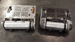
Drum Spinner
This weapon is a spinning solid cylindrical drum with teeth at the front of the robot. It is driven similarly to a vertical or horizontal spinner with a pulley system between the weapon and weapon motor.
Pros
- Great beginner bot
- Reliable due to simple weapon
- Outputs good damage
- Weapon doesn't require too much space away from the rest of the bot
- Easy to design so it can drive while flipped
Cons
- Smaller strike zone
- Gyroscopic effect can make fast turns hard
- Large heavy weapon
Example Drum Spinners designed and built by RoboJackets
Horizontal Spinner
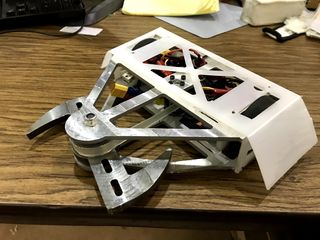
The weapon is a flat spinning bar or disk at the front of the robot. It is also driven similarly to a drum or vertical spinner with a pulley system between the weapon and weapon motor.
Pros
- High damage output
- Large strike zone
- Easy to design so it can drive while flipped
- Weapon can withstand significant damage without breaking (bent weapon still functions well)
Cons
- Robot must extend out to avoid its own weapon
- Gyroscopic effect make turning fairly difficult
- Needs a lot of structural support on the weapon to prevent damage from recoil
Example Horizontal Spinners designed and built by RoboJackets
- Ki - Competed at Sparkfun 2016 and Motorama 2017
- Chewi - Competed at Motorama 2018, RoboGames 2018, and Sparkfun 2018
- Daddi - Competed at Motorama 2019
Vertical Spinner
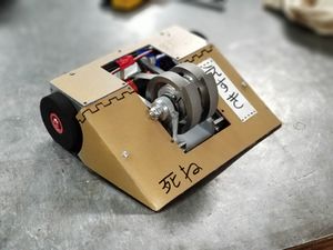
A robot with a vertically spinning weapon at the front of the robot. Typically this weapon is complemented by a surrounding wedge to lift opponents into the weapon. It is also driven similarly to a drum or horizontal spinner with a pulley system between the weapon and weapon motor.
Pros
- Great damage output
- Allows for the use of a wedge, which acts as armor and directs bots into the weapon
- If the weapon breaks, it still functions as a wedge bot
Cons
- Hard to allow for driving when flipped
- Gyroscopic effect can make driving difficult
- Weapon has to be smaller to maintain a low center of gravity (keep the bot short)
Example Vertical Spinner designed and built by RoboJackets
- Esci - Competed in Motorama 2018 and RoboGames 2018
Ring Spinner
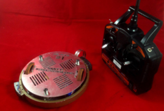
This weapon is a spinning ring with teeth that surround the entire frame. Generally, the ring is supported by "rollers", which have bearings to reduce friction and support the ring with a male-female interface. The ring is typically driven directly by the weapon motor, which has a casing of a high friction material such as rubber.
Additionally, there is a variant of the Ring Spinner called the Shell Spinner. The Shell Spinner is nearly identical to the Ring Spinner, except instead of a "ring" that is spun around, the entire robot is covered in a shell, which is spun. This allows for even more weapon coverage, at the cost of more weight being required for the larger shell, as well as the need for a stronger motor to spin it.
Pros
- Perfect 360 strike zone
- Hard to compete against
- Easy to design so that you can drive while flipped
Cons
- Difficult to design and assemble
- Weapon takes all the blows and can break
- Can be difficult to drive
Example Ring Spinners designed and built by RoboJackets
- Qti - Competed in Motorama 2017
- Smitti Werbenjagermanjensen - Competed in Motorama 2015
Wedge
The weapon is the bot itself with the main structure forming a wedge with the intent on trying to flip over, or lift the enemy bot off the ground.
Members of the RoboJackets Battlebot team do not build Wedge's because there is no real design challenge in designing a Wedge, and RoboJackets values the educational experience of designing a more complex robot. Building a more complex robot allows you to learn engineering skills that scale to more advanced competitions. Ultimately, while Wedge bots may be good at winning competitions winning the competition isn't the goal. The true goal is to learn about the design process and have fun!
Pros
- Very simple to build
- Can be built incredibly strong due to a heavier structure, thanks to the lack of a traditional weapon taking up valuable weight.
- Doesn't have a weapon that would produce a gyroscopic effect that would inhibit driving. Being able to drive easier allows the driver to be more aggressive, which judges often favor when determining a winner.
Cons
- Doesn't challenge your engineering abilities as much as a bot with a traditional weapon.
- No true destructive power which means if the enemy cannot be flipped or lifted, winning will be very difficult.
Design Process
Introduction
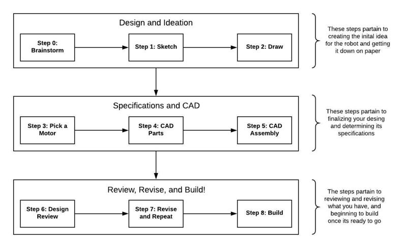
Now that you have selected a robot type, you're ready to start designing and building! The following is a detailed explanation of the design process for the RoboJackets BattleBots team. While this is specific to our team, it can be used as a general guide for any team that wants to improve their design process.
Being successful in competitions starts with the design process. While everyone wants to immediately jump into machining and get their bot done, without a proper design process the end result will be ineffective and probably nonfunctional. Additionally, without a proper CAD assembly with accompanying dimensions machining will not result in usable parts. So while it might not be as exciting as machining and assembling, it pay off in the end. Spending extra time on the design process will highly increase the quality of your final design and assembly.
Step 0: Brainstorming
The design process begins unofficially with brainstorming. Once you have an idea about what type of bot you want to build
- Research notable examples of that type of bot.
- Look for examples with different types of weapons, armor, and drive systems.
- Try to find some videos of these bots actually competing.
- See what works and what doesn't about different designs.
Once you've seen enough through researching different robots...
- Start piecing together your ideas into complete concepts once you've seen enough.
- Do a rough sketch of the shape of the chassis, weapon, etc.
- If there are some unique features on your concept, write out some notes so that when you or your team revisit it, it will be more easy to understand.
Don't limit yourself to just one idea either, the more ideas you bring to your team during the first few meetings when you decide on an overall design, the better. It is worth mentioning that you will be on a team, so don't get TOO attached to one idea, as not one person on the team will end up having designed the entire bot.
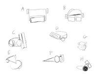
On the right, you can see an example of what good brainstorm sketches look like. There are many ideas drawn out, with a variety of features demonstrated between them. Things to focus your brainstorming on would include...
- Weapon type
- Weapon shape
- Drive system
- Overall shape
- Armor
It's important to note that no idea is a bad idea during the brainstorming phase. Any and all ideas are beneficial. While a given idea may not work, when you gather with your team you may find that a teammate will have an idea that could take a not so good design and make it great. Additionally, you may find that your team will go back to these brainstorming ideas for inspiration to solve issues with the design way down the line. In other words, the more ideas you come up with and put down on paper, the better!
Step 1: Sketch
This is when the design process will start properly. Once you're on a team, the first goal is to come up with a bot design. Think broad. Focus on features. The design process is iterative, so you will make changes to this design. However, this doesn't mean that it's not worthwhile to come up with some rudimentary overall dimensions, such as the overall length, width, and height of the bot. These dimensions can be based loosely off of previous bots as a guideline.
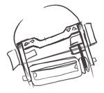
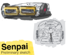
On the right, there are two examples of sketches that would be created during this stage in the design process.
The top sketch is a good example of what should be drawn at the start of the sketching step. As a team, you will produce several of these sketches, each time adding more details as you discuss the design. As you can see this top view shows the approximate location of the frame, wheels, motors, and weapon. Details such as fasteners and electronics are not yet included, as this sketch would be developed before those are considered. It is important to work out details in a logical order.
- Start with a sketch similar to those in the brainstorming phase and work out how the structure would work.
- Add in larger important things like the weapon and armor.
- Add in smaller important things like the motors, wheels, and belts.
- Add in the fine details like wires, electronics, and fasteners.
This process will allow you to logically work through taking a concept in your mind and putting it onto paper.
As more details are finalized, the sketches will become increasingly complex. Eventually, your team should have a detailed final sketch, such as the bottom example. As you can see, most if not all components are included. Multiple views are included as well, which will significantly help with visualization of the final design. It's noteworthy to see that while the sketch is incredibly detailed (and no you don't need to be an artist, most final sketches won't look this good), it still wouldn't be enough to jump directly into CAD. That's why we have the next step!
Step 2: Draw
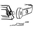
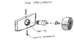
Once you've got an overall sketch of the bot, its time to start drawing some individual parts out and assign them some dimensions. This is important, as having some predetermined dimensions will make the CAD process easier. Make sure that your team is communicating during this process, as its important that everyone understands the dimensions so that any given member could make the CAD part for any given part. The more your team understands the dimensions you define, the faster and more efficient the CAD process will be. Additionally, drawings should be made that give explicit details in areas of the bot that have complex assemblies and sections of the bot. Having these draw out ahead of time will expedite the process of translating the drawing into a CAD assembly.
You will also have to determine what material the parts are made out of. See the Commonly used materials section for more details
Another thing to consider during this time is how you will attach the parts into a complete assembly. Consider using a puzzle-fit, the number of screws used to connect two parts, location of holes, and size and type of screws. Beware intersections of screws, and don't have so many screws that your part is completely filled with holes, or "Swiss-cheesed".
The top right image shows a detailed drawing which provides details about the materials and assembly of a given joint. Without this drawing, just using the final sketch, it would have been much harder to translate this isn't CAD.
The middle right image shows a detailed drawing for the assembly of the motor and the motor mount. Once again, the added details would make it much easier for the creation of the part in CAD.
This step can be done simultaneously with Steps 3 and 4, as you draw and dimension parts as you need them during the early meetings. However, it's important not to put off finishing the drawings for all parts, as it can make it harder to work outside of meetings. There should always be a group present when dimensioning parts, so if you don't have any parts that are dimensioned, you can't make a good CAD part.
Step 3: Picking a motor
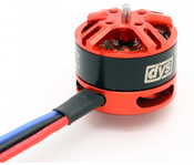
When picking a motor, there are 3 things to consider. The motor properties (things specific to the motor you cannot control), the design properties (things specific to your design you can control), and the desired specifications (specifciations that you want in the end). Motor properties you cannot control:
- KV (RPM/V): This will be used alongside our voltage value to find the Rotations Per Minute (RPM) of the motor.
- Power (W): This will be used alongside our calculated RPM value to find the Force and Spin-up time for the weapon. This value is typically between 500-800W.
- Max Current (A): This is an important number to know, as it will affect which ESC you need. The greater the max current, the bigger and heavier ESC you will need, so aim for a low max current.
- Max Voltage (V): This will be used alongside our KV value to find the RPM of the motor
- Dimensions: The size of the motor is also an important factor to keep in mind, as a large motor could force you to build a larger bot to house it. A larger bot will end up needing thinner, smaller, and weaker walls to keep the weight below 3 lbs.
- Weight: Obviously the weight of the motor matters, as a heavy motor will make it harder to build a sturdy bot due to the use of less heavy but weaker walls.
Please note that some websites have a bad habit of listing the dimensions and weight of the box the motor comes in, rather than the motor itself.
Also, be aware that many of the values provided by websites are the theoretical maximums, and won't be what you actually observe. However, for the sake of these calculations, you can just use these values.
Design properties you can control:
- Gear ratio: The gear ratio is the ratio of the diameter of the motor to the diameter of whatever you are rotating, like a pulley or the weapon drum. This will be an important factor, as it will determine the RPM of the weapon.
- Mass Moment of Inertia (J): This will be used in your calculations for Force and Spin-up time, and it can be found by making the weapon in Inventor, then checking its physical properties.
End Specifications that you desire:
- Weapon RPM: This will be an important factor for your over destructive capability. For smaller spinning weapons, such as a drum, RPMs greater than 8000RPM are desirable. For larger spinning weapons, such as a bar, RPMs between the range of 2000-5000RPM are desirable. This number is lower than the smaller weapons because if you RPM is too high with a bar spinner, you risk significant recoil when you hit the enemy and severe gyroscopic effects inhibiting responsive driving. Its one thing to rip the opponent's bot in half, but if you destroy your own bot in the process it's meaningless.
- Spin-up time (s): This value represents the amount of time required to get the weapon from rest to its max RPM. The first to strike in the competition will often gain the immediate upper hand and if the enemy bot runs into your weapon before its spun-up completely, you will deal little to no damage and the weapon will once again need to spin-up from rest again. Keeping this value as low as possible is incredibly important. In general, a Spin-up time of around 1 second would be reasonable, but ultimately it's up to your team to make the call on what you think is an acceptable amount of time.
- Kinetic Energy (J): This value represents the actual energy that your spinning weapon will produce, and therefore transfer into the other robot.
As part of getting these values, you will have to calculate several more values. The process by which you calculate these values and the ones mentioned in this section can be found below in the Calculations section of this guide.
Also, it is worth mentioning that these values that we calculate are fairly simplified, and there are many more factors that will affect the true values of these factors, however for the sake of choosing a motor, an approximate value will suffice.
Step 4: CAD Parts
This step will actually start at the same time as you're looking at choosing a motor. As part of your calculations, you will need the weapon to made in Inventor so that you can get its Mass Moment of Inertia. From there you will need to create a part for the motor that your team ends up choosing, using the dimensions and weight provided by the website you found the motor on.
Remember that the parts will need to be manufactured from stock, so once you have determined a way to manufacture a part, check how much the stock you'd need will cost and how much material will be wasted as part of your manufacturing. For example, if you have a part that you know how you could manufacture, but it would require a $100 chunk of aluminum, most of which is removed in the process, maybe look at redesigning the part to be simpler so it can be manufactured with cheaper stock. Here are some tips for making combat robot parts in CAD...
- Assign dimensions in a way that makes it easy to go back and change the values later. This is often accomplished by avoiding making dimensions all dependent on each other, and instead of keeping them based off of the part's overall dimensions.
- Utilize any standardized CAD parts for things like electronics that may be provided either online or by a mentor. This will save you the time that would be spent making the part yourself.
- Assign the material property of a part, to ensure that it's reported weight is correct. The default "generic" material will not accurately report your weight, which will result in you being overweight once everything is built. You also may find that you have only made half of the parts you need, and the overall weight is already too high. With this information, you can go ahead and adjust the dimensions of the parts you've already made to reduce the weight.
- Begin working on your assembly earlier rather than later! You don't need to actually have every single part in CAD before you start putting parts into an assembly. See the next step for more information!
Proper CADing is a team effort, not a solo endeavor. When you work alone, you risk misinterpreting a dimension or drawing. During meetings, one or two people should be actively working on the CAD with the remaining members talking through the process with them. Communication is key! You will end up creating quality uniform parts only by working together. Taking turns working on parts is also important, to ensure everyone gets time working with Inventor. Please remember that it is expected that your team will meet and work outside of our regularly scheduled meetings!
Step 5: CAD Assembly
Once the parts are made, its time to start putting together an assembly. You'll need to completely finish the assembly before you can undergo a design review. There are several "Do's and Dont's" to consider with the assembly...
- Do focus on making sure the overall weight is below 3lbs. It's important to have an assembly that is not only below 3 lbs but is safely below 3 lbs.
- Do account for the weight of things potentially not present in the assembly, such as wires, connectors, and material imperfections.
- Do add in the fine details like screws and clearances between parts to account for inaccuracies when cutting out parts.
- Do create sub-assemblies, which will allow your team to work on multiple aspects of the robot simultaneously.
- Don't assume that something can be left out of the final assembly. The assembly should include every feasible component as the real thing.
- Don't assign random colors and textures to parts. This will make it harder for people to understand the intended materials from appearance alone.
- Don't underestimate the amount of work required to put everything into an assembly. Oftentimes new issues will present themselves after putting everything together.
- Don't make all changes in the same assembly. Save copies of your assembly along the way, so you can reference the old versions if need be.
During this time, it is also important to begin working on a Bill of Materials, or BOM for short. This BOM will be a master list of the materials required to create the robot, and where they can be purchased. While there is no specific format for a BOM, the following are expected to be included in one...
- Dimension of stock plates/sheets required to manufacture parts.
- Quantity of non-stock materials such as screws, bearings, and belts.
- Sources for where the materials can be purchased.
- Any necessary notes related to the parts and materials needed.
Keeping an accurate and through BOM will allow you to launch directly into manufacturing as fast as possible after the design is complete.
Step 6: Design Review
The whole design process is leading up to one thing: The Design Review. During the design review, you will present your team's assembly to the rest of the BattleBots team. Both your peers and the senior members will ask you questions about your design and point out design flaws and recommendations on how to address them. Often times your first design review will be fairly harsh, with senior members finding plenty of issues with your design. While this may seem mean-spirited, they are simply trying to help you build the best bot that you can. The larger bots will often undergo the design review 3-5 times before they are finally approved to start machining, so even the senior members have to go through this process. Because the 3 lb bots are much simpler, usually only 2 design reviews will be needed.
It's important to take notes during the design review, as even a "good" design review will result in enough changes that you'll need to write them all down. You will likely get a lot of feedback, and while in the moment you may feel like you'll remember it all it will be impossible to remember every little comment.
Step 7: Revise and repeat
Once you get out of a design review, it's important to strike fast while the iron is hot. After your first design review, there will more than likely be several huge changes that you'll need to make to both your individual parts and the assembly as a whole. There is NOT a lot of time between the first and second design reviews (often only a week or two), due to the natural time constraints of the 3lb program. So it's important to start working on these changes sooner rather than later. It's important to also make sure you address ALL the things that are mentioned during the review, as it's important not the waste everyone's time with repeat issues from the previous review.
Step 8: BUILD!
Now finally you can begin manufacturing! Keep in mind...
- You will need to make minor adjustments to the design as you manufacture, and when you do so make sure to update your CAD to reflect these changes.
- Beware changing too much and causing the overall assembly to be overweight.
Calculations
Below is a step by step guide on the calculations required to determine what motor to choose for your bot. Keep in mind these calculations are fairly simplistic and don't take several real-world factors into account. Additionally, these values will be computed based off of what is reported by the manufacturers, which are often "best case scenario" and are not what you should expect to see in practice.
Step 1: Get values for the motor
The first step is to retrieve the following values off of the distributor/manufacturer's website.
- KV: Motor Velocity Constant (RPM/V)
- P: Power (W)
- V: Voltage (V)
Step 2: Determine values regarding the weapon
The next step is to determine a few values from your design of the weapon.
- J: Mass Moment of Inertia (lbf*ft*s^2)
- e: Gear Ratio (Drive gear/Driven gear)
Step 3: Determine intermediary values
In order to calculate our desired values, we need to calculate some intermediary values to use in our later calculations.
- ω: Angular Velocity (rad/s)
- RPM: Rotations Per Minute
- τ: Torque (lbf*ft)
RPM = KV * V
ω = RPM * (2π / 60)
τ = P / ω
Step 4: Adjust values according to gear ratio
Some of our values need to be adjusted according to what gear ration is being used between the motor and the weapon.
ωoutput = ωinput * e
τoutput = τinput / e
For the calculations past this point, please use these new "output" versions of ω and τ in place of our old values.
Step 5: Get our desired values
Finally, we are ready to calculate the final values that we actually want!
- KE: Kinetic Energy
- t: Spin-up Time (s)
KE = 0.5 * (ωoutput ^ 2) * J
t = 3 * ((0.63 * ωoutput * J) / τoutput)
Standard Robot Components
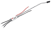
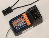
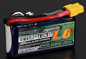
Provided below is a table containing information on some of the standard components found on nearly every 3lb combat robot.
Commonly Used Materials
In this section, I will describe some of the most common materials used to build a 3lb combat robot. Aluminum, Steel, and Plastic are the most commonly used materials for building a 3lb robot. While there are a few more materials that some teams use (e.g. carbon fiber or titanium), these three materials are affordable, lightweight enough to be used in a 3lb combat robot, common enough that they can be easily purchased from a variety of sources, and strong enough to be used in for combat.
Aluminum
Common Uses
- Majority of structural pieces
- Any non-striking surface that needs to be strong
- Drum for drum spinners
Features
- Moderately light
- Moderately strong
- Good all-purpose material
Aluminum is one of the most commonly used materials for building a combat robot. This is because it is lightweight but strong enough to be used for the core structure of the robot.
The most commonly used aluminum alloys are 6061 and 7075. Below are some of the advantages and disadvantages between these two alloys,
| 6061 Aluminum | 7075 Aluminum | |
|---|---|---|
| Advantages |
|
|
| Disadvantages |
|
|
RoboJackets typically sources its aluminum from Midwest Steel Supply and McMaster-Carr. A 12" x 12" x 0.25" plate of 6061 aluminum costs approximately $22.
Steel
Common Uses
- Screws and fasteners
- Weapon teeth for drum spinners and ring spinners
- Overall weapon for vertical and horizontal spinners
- Any striking surfaces
Features
- Very strong
- Very heavy
- Great for resisting deformation
Because of its heavyweight, steel should be used sparingly, and it is typically reserved for the part that strikes the enemy robot. This is to ensure that all of the energy of the collision is transferred into the enemy bot, and not into deforming your weapon. Additionally, steel is often utilized as the striking surface on the weapon.
The most common type of steel used is low-carbon steel as it is easy to machine, strong, and fairly cheap.
RoboJackets typically sources its steel from Midwest Steel Supply and McMaster-Carr. A 12" x 12" x 0.25" plate of steel costs approximately $40.
Plastic
Common Uses
- Disposable armor pieces
- Any part that won't experience stress
- Internal walls to prevent contact between various components
Features
- Very light
- Reasonably strong
- Deforms easily
Plastic is a fantastic material for armor, as it is lightweight, cheap, and surprisingly strong! Armor on a 3lb combat robot is not supposed to be rigid, and strong, as that means whatever energy that is transferred into the armor gets then transferred into the robot's structure. Plastic dissipates the energy that is passed into it by breaking and being ripped apart. Due to the low cost and high machine-ability, you can manufacture several sets of armor pieces and replace them as they are broken. This is much better than having to manufacture and replace core structural components!
The most commonly used type of plastic used is High-density polyethylene (HDPE) because it provides a high strength-to-weight ratio and is fairly elastic. When used as armor, HDPE plastic will "bounce" most glancing blows off of your robot.
RoboJackets typically sources its HDPE plastic from McMaster-Carr and ePlastics. A 12" x 12" x 0.25" plate of HDPE costs approximately $8.
Helpful Links
- List of 3lb Robots - List previously built robots, sorted by robot type
- Electronics Basics - Guide to the basics of the electronics typically used
- 3lb Documentation Guide
- 3lb Design Log Guide
