Difference between revisions of "2016 Electrical Encoder"
Jump to navigation
Jump to search


(Tag: Visual edit) |
(→Notes) (Tag: Visual edit) |
||
| Line 97: | Line 97: | ||
== Notes == | == Notes == | ||
Test bench in progress. | Test bench in progress. | ||
| + | |||
| + | == Other Components == | ||
| + | * [[2016 Electrical Flow Chart|Flow Chart]] | ||
| + | * [[2016 Electrical Motor Shield|Motor Shield]] | ||
| + | * [[2016 Electrical OSMC|OSMC]] | ||
| + | * [[2016 Electrical Motor|Motor]] | ||
| + | * [[2016 Electrical Motor Fuses|Motor Fuses]] | ||
| + | * [[2016 Electrical E-Stop|E-Stop]] | ||
| + | * [[2016 Electrical Shunt|Shunt]] | ||
== References == | == References == | ||
Revision as of 22:34, 9 November 2016
Contents
Rotary Encoder
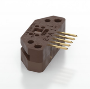
Converts angular motion into a digital signal using two square waves in quadrature (90° out of phase). Using one for each drive wheel allows for accurate measurement of speed.
Connections (5-pin header)
|
Pin |
Function |
Signal Type |
Connected Device |
|
1 |
Ground |
GND |
Motor Shield |
|
2 |
-- |
-- |
-- |
|
3 |
A |
digital |
Motor Shield |
|
4 |
Power |
VCC (5V) |
Motor Shield |
|
5 |
B |
digital |
Motor Shield |
Datasheet

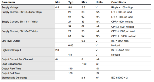
Encoder data table<ref>http://cdn.usdigital.com/assets/datasheets/EM1_datasheet.pdf?k=634991170254798537</ref>

Encoder data table<ref>http://cdn.usdigital.com/assets/datasheets/EM1_datasheet.pdf?k=634991170254798537</ref>
Notes
Test bench in progress.

