Hocki
| Hocki | |
|---|---|
| Year Of Creation | 2020-2021 |
| Versions | |
| Current Version | 1.0 |
| Update Year | 2020-2022 |
| Wins/Losses | 1/2 |
| Information and Statistics | |
| Weight Class | Hobby Weight |
| Weapon Class | (Translational Drift Spinner/Meltybrain) |
| Combined Wins/Losses | 1/2 |
| Weapon Speed | 3600 RPM |
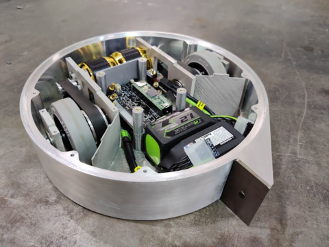
Hocki is a Meltybrain, a combat robot that spins itself to attack. Unlike other robots, which have a stationary frame and spinning weapon, in this robot the entire frame is the weapon, and the robot spins itself to attack. This allows the robot to store more energy while spinning slower, which allows for hits to connect better. Such a design requires a control system which uses sensors to estimate the position of the robot. This robot utilizes custom circuitry and software to allow the frame to move, spin, and attack.
Contents
Competitions
Due to COVID-19 this robot did not go to competitions.
Design
(Hocki) V1.0
Team Lead: Valentin Richter
Team Mentor: Varun Madabushi
Members: John Bowzard, Kevin Xiao, Madeline Belew, Steven Zhao
| Drive Motors | Scorpion HKIV-4020-860KV |
| Drive Motor Controllers | iFlight SucceX X80A |
| Receiver | FS-A8S |
| Remote Control | FS-i6X |
| Battery | 2x Turnigy Graphene Panther 1200mAh 6S 75C Battery Pack w/XT60 |
| (OTHER:) |
Mechanical
Overall Design and Construction
The robot is comprised of an aluminum ring with aluminum top and bottom plates bolted on. All interior components (electronics, drive assembly) are sandwiched between the two rings.
One priority in the design is increasing the moment of inertia as much as possible by moving heavier components outwards. The main structure of the robot is the aluminum ring, which is CNC machined out of a single piece. This CNC machined part was ordered from Xometry due to obstacles in HAAS training and shop access due to the COVID-19 pandemic. After receiving the ring, it was tapped to accept screws which hold the top and bottom plates as well as the impactor tooth. The top and bottom plates were machined on the waterjet cutter and sanded to fit the grooves in the ring, as well as the motor and wheel mounts.
Another priority is keeping the center of mass centered at the midpoint of the wheels. If it were not, the kinematic center of rotation would be far from the dynamic center of rotation, resulting in drift and preventing the accelerometers from accurately measuring the centripetal acceleration. Thus care is taken in the placement of interior and exterior components to balance the robot.
We selected a 1-tooth design as the 1 tooth can cancel the weight of the motors in the back.
Drive
Describe structures/mechanisms here such as Drive, Ring, yada yada
Mounting
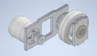
Drive train mounts screwed into both top and bottom plates and allow for assembly of wheel, motor, and pulley system.
Thermal pads used to adhere ESCs to bottom plate. Thin metal bar screwed to bottom plate above ESCs to improve stability and limit movement. PCB holder screwed into bottom and top plates. PCB is mounted onto 3D-printed PCB holder using 4 screws and rubber spacers.
Electronics
Overall Design
Control Board
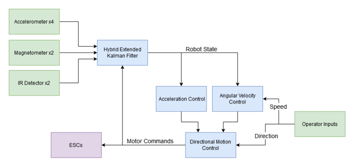
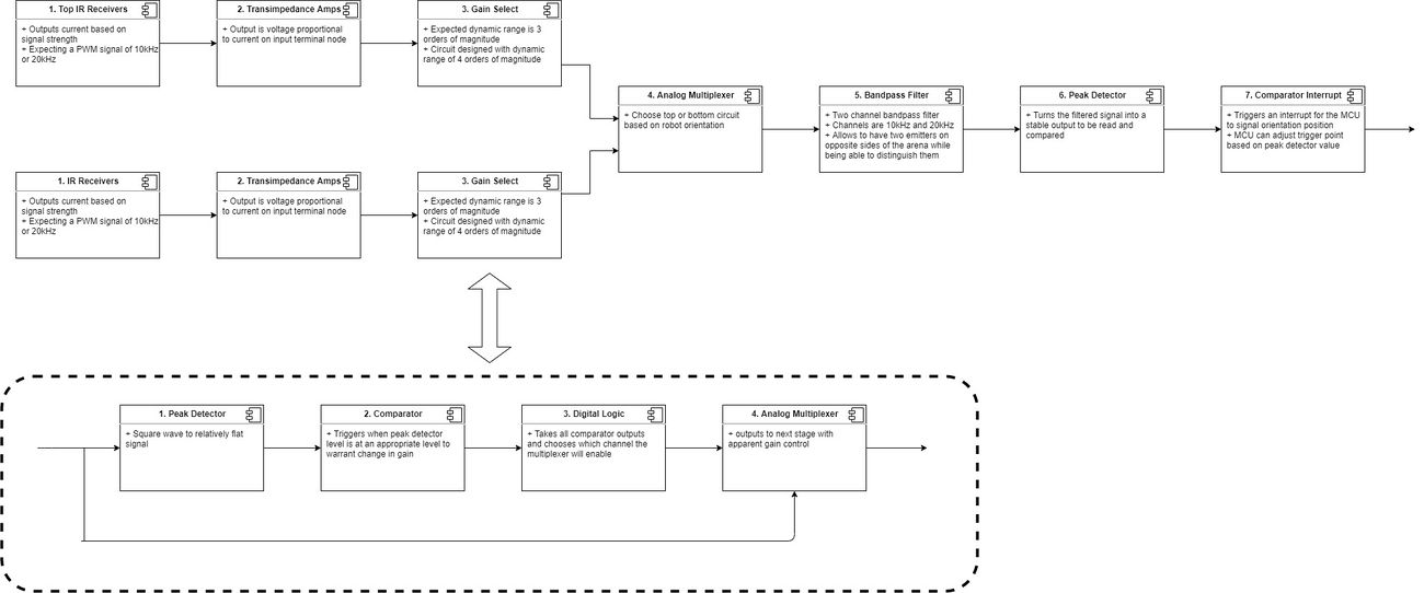
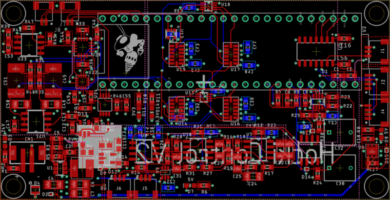
The control board is mounted at the heart of the robot and connects to the LED, IR receiver, and ESC boards. On the control board, there are 4 accelerometers, 2 magnetometers, a 10 kHz bandpass filter, and a 20kHz bandpass filter. It also connects to a Teensy 4.1, which acts as a microcontroller and data logger. The bandpass filters are part of the IR Detector.
Due to electrical failures that could not be remedied during the chip shortage, the magnetometers and bandpass filters were not utilized for Motorama 2022. The design of 4 accelerometers is 3 more than typical translational drift robots have, which allows higher accuracy from the reduced sensor arsenal. During the competition, the first version of the board had to be used after shorts caused the regulator subsystems of the V2 boards to fail.
Key differences between the first and second versions of the control board are that the second version supports the complex LED board and that the accelerometers are not at a 45° angle to the board. The accelerometers, which are located around the estimated center of mass and rotation of the robot, would have been oversaturated at the 45° angle if the bot spun up to the theoretical RPM, which is not possible due to that calculation ignoring drag.
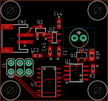
IR Transmitter/Detector
The IR subsystem is comprised of a transmitter (left) and receiver (right). The transmitter is controlled by an ATtiny84 programmed to operate an IR LED at either 10 kHz or 20 kHz outside of the arena. The receiver then has 4 diodes set at differing gains to amplify the signal as necessary so that within the bound of the arena, at least one of the 4 will provide a strong enough signal to the bandpass filter on the control board.
The subsystem encountered noise from other IR sources during testing. The bandpass filters were removed before they were tested in order to have a functioning control board for Motorama 2022. A lesson learned from the board is to be careful with programming microcontrollers, as Xtal settings can cause them to break just as easily as shorting them or running them at the wrong voltage can.
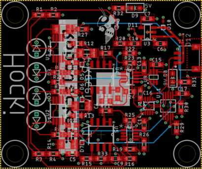
LED Board
The 8 RGB LED board is only compatible with the V2 control board, but it offers customizability in relaying bot status to the driver. LEDs on the ends sometimes failed, and in the future, only 3 RGB LEDs will likely be used. For Motorama 2022, a red LED was used as the only means of indication.
Software
Overall Design
Low-Level Systems
Controls and Data Logging
We derived equations to calculate rotational velocity from measured centripetal acceleration without needing to know the exact center of mass by using data from a pair x or y measurements from the accelerometers. With this method, we calculated four rotational velocities and averaged them to find the rotational velocity of the robot with minimized noise. We then integrated this velocity to get the angle the robot was oriented, setting zero to be the initial direction the robot was facing. However, even with this method we found that the position of the robot would drift at rest but was relatively accurate at higher rotational speeds.
To translate while spinning, we alternated pulsing the left and right motor speeds, each for half of a rotation, which is illustrated in the below image. However, during competition we were not able to translate in a controlled direction, rather translating in one random direction regardless of controller input.
We logged each axis of every accelerometer, as well as the average rotational velocity and the position of the robot at a frequency of 20 Hz. We stored this data in a .txt file on an SD card inserted onto the Teensy board. For the logging, we added 16 lines of data to a buffer before flushing the lines to the file.
See also
Notes:
Named after its resemblance to a hockey puck
Original Builders: Afshan Chandani, Varun Madabushi, Juan Elizondo, Hank Hellstrom, Darren Kosen, Nelson Jiang, Valentin Richter, Kevin Xiao, Sarkis Ter Maritorsyan, Keaton Sadoski, Alex Yu
