Difference between revisions of "Valkyri Design Guide"
Ntranakiev3 (talk | contribs) |
Ntranakiev3 (talk | contribs) |
||
| Line 1: | Line 1: | ||
| + | |||
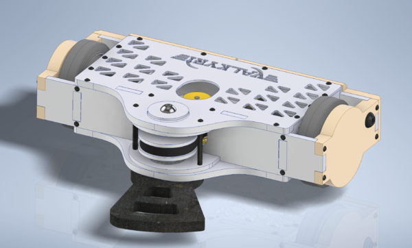
| + | [[File:Valkyri.png|right|thumb|600px|Valkyri CAD]] | ||
== Introduction == | == Introduction == | ||
Valkyri is a 30lb undercutting horizontal spinner developed during the 2019-20 season for the Robobrawl competition. It was meant to implement innovative features for Battlebots such as magnets and a direct drive system but was never able to compete. | Valkyri is a 30lb undercutting horizontal spinner developed during the 2019-20 season for the Robobrawl competition. It was meant to implement innovative features for Battlebots such as magnets and a direct drive system but was never able to compete. | ||
| Line 15: | Line 17: | ||
Bot Friend: Carrie Wehmeyer | Bot Friend: Carrie Wehmeyer | ||
| − | |||
| − | |||
| − | |||
| − | |||
Revision as of 12:47, 8 May 2020
Contents
Introduction
Valkyri is a 30lb undercutting horizontal spinner developed during the 2019-20 season for the Robobrawl competition. It was meant to implement innovative features for Battlebots such as magnets and a direct drive system but was never able to compete.
Team Members: Bot lead: Nikolay Tranakiev Judea Britt Celina Huang Grace Khan Hoyean Le Paul Matesevac Tyler Mesa Keaton Sadoski
Bot Friend: Carrie Wehmeyer
Design Basics
Chassis
Overview
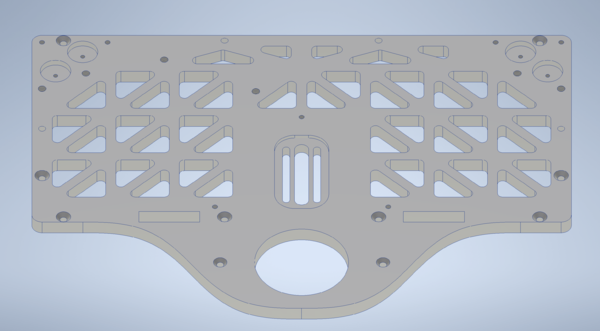
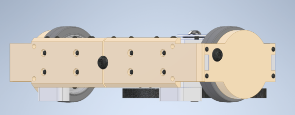
Valkyri’s chassi consisted of 8 components: top and bottom plates, right and left inner side plates, front and back plates and weapon mounting plates.
Design Decisions
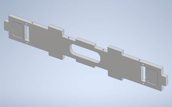
Front Plate (.375”): The front plate puzzle fit into the side, top and bottom plates. In order to move the weapon closer to the body and have the correct pulley ratio, it overlapped slightly with the front plate and required a large cutout. This made disassembly more difficult but did not cause issues during brief testing. The plate extended beyond the sides of the top and bottom plates and puzzle fit with the side armor. Two pockets were also added so that the wheels could be moved further forward and closer to the center of gravity without rubbing on the plate. Machining was mostly straight forward but the plate was too long to be able to machine the holes for the side armor on the mill so a custom jig was waterjet and the holes were hand drilled.
Back Plate (.375”): The back plate was similar to the front plate but it lacked puzzle fits into the top and bottom plates and a hole for the pulley. It had additional tapped holes for attaching the back armor and on the inside for attaching the switch. It also required hand drilling for the side armor mounting holes similar to the front plate.
Side Plates: (0.5”) The side plates were made slightly thicker since they were the attachment point of the drive motors and therefore held the weight of the bot. They also included more cutouts to save weight. The motor pocket was initially circular with a rectangular portion for wire management since the brushless motors were attached directly to the plate. The shallowness of this pocket may have contributed to the wiring issues on the second iteration of the drive (See drive section). The second iteration of the side plates (for the third iteration drive) had a large rectangular pocket to fit the gearbox mounting plates.
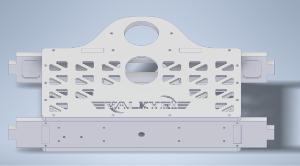
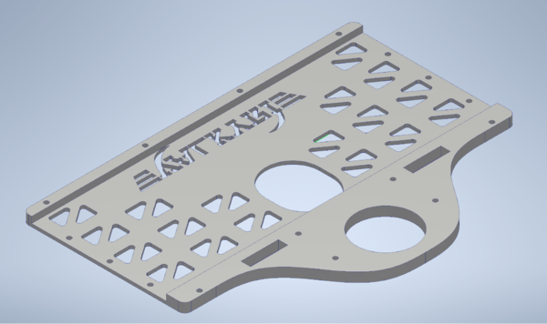
Top Plate (.0375”): The top plate was made of ⅜ aluminum since it was the upper attachment point of the weapon but the central part behind the front plate was milled to .125” to save weight and since it was assumed there would be no significant forces acting on the top of the robot. Most of the structural rigidity came from the front, back and side plates.
Bottom Plate: (0.375”) The bottom plate was the heaviest part of the chassis. It was ⅜” over its entire area. It was also the attachment point closest to the weapon and therefore assumed to take the most force. There were 4 pockets in the back corners as seats for the magnets. Several of the screws on the bottom plate were countersunk so that they would not be hit by the weapon as it spun. Since the weapon motor needed to be moved to tighten the belt and therefore countersunk screws could not be used, a large slot pocket was created at the mounting slots to ensure they would not be struck by the weapon.
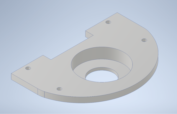
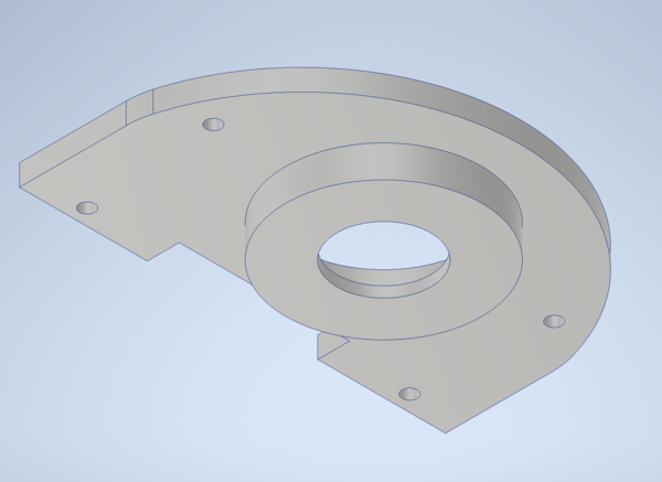
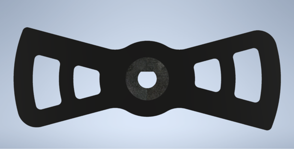
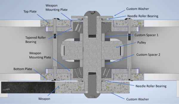
Weapon mounting Plates (.625”): Originally the weapon bearings were meant to press fit into the bottom and top plates. However, tapered roller bearings for the 1” shaft were too thick and would have required at least a .625” thick bottom and top plate which would have weighed too much. Another option considered was using .625” bottom and top plates and then milling the back portion to .375 but that was deemed as too difficult of an operation with too much material being removed.
The weapon mounting plates fixed these problems by being a separate part in which the bearings fit which then puzzle fit into the bottom and front plates. The bearing was press fit into the plate and the plate was a relatively loose fit into the bottom plate so that it could be removed and disassembled. The plate was in total .625” thick but .75” stock was used to allow for better work holding. The outline and center hole of the part was waterjet and the rest was completed on two operations with the HAAS. 7075 Aluminum was used since there was available stock and machining was not significantly more difficult since it was CNCed anyway.
Armor
Overview
Valkyri’s armor consisted of 4 HDPE components: two .75” side plates, and two .5” back plates.
Design Decisions
The primary objective or the armor was to prevent direct damage to the chassis. The back armor was fairly thin and divided into two pieces so that it would be easier to replace when damaged. The side armor featured a slightly rounded profile in order to provide some protection to the wheels in the case of being against another undercutter. Large ½-20 button screws were placed in the middle of the armor pieces (one on each side and one on the back). This was done in order to make the possibility of the bot landing on its side less likely although the effectiveness of this design choice was never tested.
Drive
Overview
test
Design Decisions
test
Calculations
test
- Notes/Helpful Advice
- test
Weapon
Overview
Valkyri used a single large horizontal spinning weapon mounted .25” from the ground. Its primary intention was to strike opposing bots below their defenses and while also being larger and more powerful than most other bots.
Design Decisions
Weapon: Valkyri’s weapon was a two toothed plate 14 inches in diameter and machined out of a single block of steel. The shape was chosen over more experimental designs since it was a good balance of high moment of inertia and strength. It has thick supports on the hitting edge but a large amount of the mass is also positioned far from the center of rotation with concentric arches. It was spun by the weapon shaft and a D slot. A 1/16” pocket was milled on the bottom in order to fit a washer that held the weapon to the shaft and prevented it from falling off. It was originally meant to be made of S7 tool steel but due to problems with the order, it was instead made of P6 low carbon mold steel. The effects of this material choice are not known since it was never tested in competition.
Assembly:
Weapon Shaft:
The weapon shaft was 1 inch in diameter and made of steel. A 1 inch diameter was chosen since It had a D profile on the bottom section to connect to the weapon and two ½” screws on the top and bottom to hold the assembly together. The pulley was mounted to the shaft with a key and a set screw. The key slot and set screw slot were machined on a mill using a collet block to ensure that they were at 90° of each other.
Tapered Roller Bearings: The roller bearings were chosen based on the diameter of the shaft and the rated max rpm. Tapered roller bearings were chosen since they support the shaft in the axial direction rather than just shear. Most bearings of this size that had documented specifications were capable of withstanding the theoretical maximum speed of the weapon (8000 rpm). The thinnest bearing available for this shaft size was chosen since that was the most limiting dimension of the design. Some bearings had ratings for the max amount of force they could withstand but they were not considered since there was no way to reliably calculate the forces created during competition.
Washers: Washers were waterjet out of 1/16” aluminum since there was not a source that sold the correct size capable of fitting the ½” screw snugly while also being wide enough to work with the needle roller bearings or weapon pocket.
Spacers: Two spacers were used to position the pulley at the correct height of the front plate slot and the weapon motor. They also helped provide axial support for the pulley. They were two simple aluminum rings of different sizes that fit loosely on the shaft. Also one was lost somewhere in the electronics room and never found…
Calculations
test
- Notes/Helpful Advice
- test
Electronics
Overview
test
Drive
test
Weapon
test
- Notes/Helpful Advice
- test
