Difference between revisions of "Emergency Stop System"
Jump to navigation
Jump to search
(Creation of page and addition of links.) |
Joldenburg6 (talk | contribs) m (Categorize) |
||
| (One intermediate revision by one other user not shown) | |||
| Line 1: | Line 1: | ||
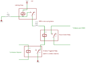
In the event of an emergency (and to comply with the official IGVC rules), the addition of a stop system is prudent. The emergency stop system is installed between the high power battery system and the open source motor controllers. Emergency stop can be activated by pressing the "Big Red Button" mounted on the back of Candi, or by triggering the wireless E-Stop. | In the event of an emergency (and to comply with the official IGVC rules), the addition of a stop system is prudent. The emergency stop system is installed between the high power battery system and the open source motor controllers. Emergency stop can be activated by pressing the "Big Red Button" mounted on the back of Candi, or by triggering the wireless E-Stop. | ||
| − | |||
| − | |||
*[http://www.aaaremotes.com/mu24vgaorgad.html Wireless E-Stop Receiver] | *[http://www.aaaremotes.com/mu24vgaorgad.html Wireless E-Stop Receiver] | ||
*[http://www.aaaremotes.com/30703060mini.html Wireless E-Stop Transmitter] | *[http://www.aaaremotes.com/30703060mini.html Wireless E-Stop Transmitter] | ||
| + | |||
| + | [[Image:ESTOP.png|thumb|right| E-Stop schematic.]] | ||
| + | {{clr}} | ||
| + | [[Category:IGVC]][[Category:2006-2007]] | ||
Latest revision as of 22:46, 13 June 2018
In the event of an emergency (and to comply with the official IGVC rules), the addition of a stop system is prudent. The emergency stop system is installed between the high power battery system and the open source motor controllers. Emergency stop can be activated by pressing the "Big Red Button" mounted on the back of Candi, or by triggering the wireless E-Stop.
