RoboCup: Control Board 2011
<parsererror style="display: block; white-space: pre; border: 2px solid #c77; padding: 0 1em 0 1em; margin: 1em; background-color: #fdd; color: black">
Contents
This page contains the following errors:
Below is a rendering of the page up to the first error.
</parsererror>
| Timeline | |
|---|---|
| Year | 2013 |
| Versions | |
| Control Board | 2011 Rev c |
| Kicker Board | |
| Main Components | |
| MCU | AT91SAM7S256 |
| FPGA | XC3S100E-TQ144 |
| IMU | InvenSense IMU-3000 |
| Motors | Maxon EC45flat 30W |
| Battery | - |
Overview
This page contains reference information for the 2011c control boards.
Quick Links
Motor Operations
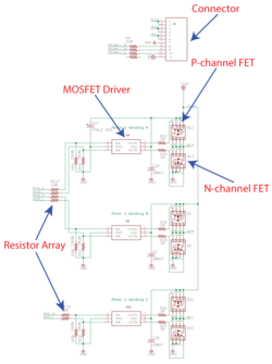
A three-phase bridge (figure 1) is the name of the circuit that is used to control each motor. The control signals for the motors come from the FPGA (XC3S100E). The robot uses 4 30W three phase brushless motors to maneuver itself on the field. A 5th motor is also used for the dribbler. In order to operate each motor with the needed precision, a brushless motor driving circuit is used for every motor. The motors also contain hall--channel MOSFET (IRF9310TRPBF) is used to connect to +12V and a n-
MOSFET Operation
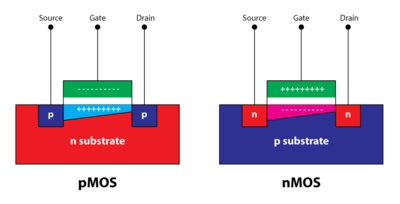
A MOSFET or Metal-Oxide-Semiconductor Field-Effect Transistor, is basically a switch. There are 3 terminals: source, drain, and gate, and figure 2 outlines the physical layout of their relations. If you apply a voltage at the gate, this will allow a flow of charges from the source to the drain. These devices use metal oxides and the charges flow due to the effect of an electric field between the source and drain. Hence why they are called MOSFET. There are 2 types of MOSFETs, nMOSFET - where the majority of charge carriers are electrons - and pMOSFET - where the majority of charge carriers are holes. The gate-source voltage must be high (positive) to turn on a nMOS and low (negative) to turn on a pMOS. This voltage is refereed to as the threshold voltage and is defined in table 1 below. The pMOS is better at pulling the output high while nMOS is better at pulling the output low; Therefore, both MOSFETs are used in the motor driver circuit - they complement one another.
| nMOS | pMOS |
|---|---|
| [[File:|V_{G} - V_{S} {\color{red} /> } V_{T}]] |

