Difference between revisions of "RoboCup: Control Board 2011"
Cwehmeyer3 (talk | contribs) |
|||
| (20 intermediate revisions by 3 users not shown) | |||
| Line 1: | Line 1: | ||
| − | <!-- INFO BOX --> | + | <!-- INFO BOX -->{{RCEEInfoBox |
| − | {{RCEEInfoBox | + | |year=2011 - 2014 |
| − | |year= | ||
|control_ver=2011 Rev c | |control_ver=2011 Rev c | ||
| − | | | + | |mcu=Atmel [http://www.atmel.com/images/doc6175.pdf AT91SAM7S256] |
| − | + | |fpga=Xilinx [http://www.xilinx.com/support/index.html/content/xilinx/en/supportNav/silicon_devices/fpga/spartan-3e.html Spartan-3E] | |
| − | | | + | |imu=InvenSense [http://www.invensense.com/mems/gyro/imu3000.html IMU-3000] |
| − | | | ||
|motors=Maxon EC45flat 30W | |motors=Maxon EC45flat 30W | ||
| + | |battery=Thunder Power [http://www.westlondonmodels.com/Electric/Battery-Packs/TP-Pro-Lite-25C/ThunderPower-TP1350-18056.asp TP1350-4SPL25] | ||
}} | }} | ||
| − | |||
== Overview == | == Overview == | ||
| − | This page contains reference information for the 2011c control boards. | + | |
| + | This page contains reference information for the 2011c control boards. | ||
== Quick Links == | == Quick Links == | ||
| − | *[[ | + | |
| − | *[[ | + | *[[Testing a MOSFET|Testing a MOSFET]] |
| + | *[[RoboCup Electrical 2014|RC Electrical 2014]] | ||
*[[RCFirmware|Firmware]] | *[[RCFirmware|Firmware]] | ||
| − | *[[ | + | *[[TDP|Team Description Papers]] |
| − | |||
== Motor Operations == | == Motor Operations == | ||
| − | [[File:RC EE three phase bridge 2011 c.png|left | + | [[File:RC EE three phase bridge 2011 c.png|thumb|left|250px|RC EE three phase bridge 2011 c.png]] |
| − | A three-phase bridge ([[:File:RC EE three phase bridge 2011 c.png|figure 1]]) is the name of the circuit that is used to control each motor. The control signals for the motors come from the FPGA ( | + | A three-phase bridge ([[:File:RC EE three phase bridge 2011 c.png|figure 1]]) is the name of the circuit that is used to control each motor. The control signals for the motors come from the FPGA ([http://www.xilinx.com/support/index.html/content/xilinx/en/supportNav/silicon_devices/fpga/spartan-3e.html Spartan-3E Series]). The robot uses four (4) 30W three phase brushless motors to maneuver itself on the field. A fifth motor is also used for the dribbler. In order to operate each motor with the needed precision, a brushless motor driving circuit is used for every motor. The motors also contain [http://en.wikipedia.org/wiki/Hall_effect_sensor hall effect sensors]. These sensors send data back to the FPGA that is used to determine a motor�s rotational position. Each phase of a brushless motor is controlled using two (2) transistors. For this application, a MOSFET type transistor is used. Although MOSFET is the appropriate technical name, it is often shortened by simply saying FET. A p-channel MOSFET ([http://www.irf.com/product-info/datasheets/data/irf9310pbf.pdf IRF9310TRPBF]) is used to connect to +12V and a n-channel MOSFET ([http://www.irf.com/product-info/datasheets/data/irf8734pbf.pdf IRF8734TRPBF]) is used to connect to ground. The I/O pins from the FPGA could power the FETs directly, but this would result in a loss of performance (the FETs could not be in their best conduction mode). Therefore, a MOSFET Driver ([http://ww1.microchip.com/downloads/en/DeviceDoc/21422D.pdf TC4428]) is used in order to ''boost'' the signal for the gate on each FET. |
| − | Each phase of a brushless motor is controlled using 2 transistors. For this application, a MOSFET type transistor is used. Although MOSFET is the appropriate technical name, it is often shortened by simply saying FET. A p-channel MOSFET (IRF9310TRPBF) is used to connect to +12V and a n-channel MOSFET (IRF8734TRPBF) is used to connect to ground. The I/O pins from the FPGA could power the FETs directly, but this would result in a loss of performance (the FETs could not be in their best conduction mode). Therefore, a MOSFET Driver (TC4428) is used in order to | ||
=== MOSFET Operation === | === MOSFET Operation === | ||
| − | [[File:RC EE Mosfet Diagram.png|right | + | [[File:RC EE Mosfet Diagram.png|thumb|right|400px|RC EE Mosfet Diagram.png]] |
| − | A MOSFET or Metal-Oxide-Semiconductor Field-Effect Transistor, is basically a switch. There are 3 terminals: source, drain, and gate, and [[:File:RC EE Mosfet Diagram.png|figure 2]] outlines the physical layout of their relations. If you apply a voltage at the gate, this will allow a flow of charges from the source to the drain. These devices use metal oxides and the charges flow due to the effect of an electric field between the source and drain. Hence why they are called MOSFET. | + | A MOSFET or Metal-Oxide-Semiconductor Field-Effect Transistor, is basically a switch. There are 3 terminals: source, drain, and gate, and [[:File:RC EE Mosfet Diagram.png|figure 2]] outlines the physical layout of their relations. If you apply a voltage at the gate, this will allow a flow of charges from the source to the drain. These devices use metal oxides and the charges flow due to the effect of an electric field between the source and drain. Hence why they are called MOSFET. There are 2 types of MOSFETs, nMOSFET - where the majority of charge carriers are electrons - and pMOSFET - where the majority of charge carriers are holes. The gate-source voltage must be high (positive) to turn on a nMOS and low (negative) to turn on a pMOS. This voltage is refereed to as the threshold voltage and is defined in table 1 below. The pMOS is better at pulling the output high while nMOS is better at pulling the output low; Therefore, both MOSFETs are used in the motor driver circuit - they complement one another. |
| − | There are 2 types of MOSFETs, nMOSFET - where the majority of charge carriers are electrons - and pMOSFET - where the majority of charge carriers are holes. The gate-source voltage must be high (positive) to turn on a nMOS and low (negative) to turn on a pMOS. This voltage is refereed to as the threshold voltage and is defined in table 1 below. The pMOS is better at pulling the output high while nMOS is better at pulling the output low; Therefore, both MOSFETs are used in the motor driver circuit - they complement one another. | ||
| − | {| class="wikitable" | + | {| class="wikitable" style="width: 350px;" align="center" |
| − | + | |- | |
! nMOS | ! nMOS | ||
! pMOS | ! pMOS | ||
|- | |- | ||
| − | | < | + | | style="text-align: center;" | <span style="font-size:larger;">V<sub>g</sub> '''-''' V<sub>s</sub> <span style="color:#FF0000;">'''>'''</span> V<sub>t</sub></span> |
| + | | style="text-align: center;" | <span style="font-size:larger;">V<sub>g</sub> '''-''' V<sub>s</sub> '''<span style="color:#FF0000;"><</span>''' V<sub>t</sub></span> | ||
|} | |} | ||
=== Single Motor Winding Circuit Explanation === | === Single Motor Winding Circuit Explanation === | ||
| − | From [[:File: | + | From [[:File:RC EE Motor Winding.png|figure 3]], ''OUTA'' is the inverting output and ''OUTB'' is non-inverting output (from the MOSFET Driver). ''Q7'' is the pMOS and ''Q8'' is the nMOS. The source of the pMOS is connected to ''VDD'' (+12V) and the drain is connected to one of the motor coils. In the nMOS, the source is connected to the motor coil while the drain is connected to ''GND''. When the signal from the FPGA is to activate one of the motor windings, ''M4C_H'' is high and ''M4C_L'' is low. So, ''OUTA'' becomes low while ''OUTB'' is still the same as ''INB''. This turns the pMOS on and the nMOS off. Doing so connects ''M4C'' to ''VDD'', thus ''M4C'' is set to high potential. At this same instant, a different motor winding circuit will connect its output to ''GND''. For example, let�s say ''M4B'' (not shown) connects to ''GND'' when ''M4C'' connects to ''VDD''. This means current will flow from ''M4C'' to ''M4B'', thus powering the motor for a short instance of time. However, we must ensure that the 3rd motor winding circuit (M4A, also not shown) is disconnected from both ''VDD'' and ''GND''. This means both FETs from ''M4A'' must be off at this instance in time. ''R128'' is a resistor which limits the current from the FPGA�s I/O pin. ''R56'' and ''R57'' are pull-down resistors that ensure ''INA'' and ''INB'' maintain a proper value if there is no signal from the FPGA. ''R54'' and ''R55'' provide signal stability for the base of each FET (the voltage could oscillate back and forth without them). ''C26'' is used to filter out unwanted high frequencies from ''VDD''. |
| − | When the signal from the FPGA is to activate one of the motor windings, ''M4C_H'' is high and ''M4C_L'' is low. So, ''OUTA'' becomes low while ''OUTB'' is still the same as ''INB''. This turns the pMOS on and the nMOS off. Doing so connects ''M4C'' to ''VDD'', thus ''M4C'' is set to high potential. At this same instant, a different motor winding circuit will connect its output to ''GND''. For example, | ||
| − | ''R128'' is a resistor which limits the current from the | ||
| − | [[File:RC EE Motor Winding.png|thumb|500px| | + | [[File:RC EE Motor Winding.png|thumb|500px|RC EE Motor Winding.png]] |
=== Debugging === | === Debugging === | ||
| Line 56: | Line 52: | ||
=== Other Websites/Resources === | === Other Websites/Resources === | ||
| − | * Youtube video explaining the operations of brushless DC motors (BLDC) - [http://www.youtube.com/watch?v=ZAY5JInyHXY|youtube.com] | + | |
| − | * PDF about more BLDC motors - [http://electrathonoftampabay.org/www/Documents/Motors/Brushless | + | *Youtube video explaining the operations of brushless DC motors (BLDC) - [http://www.youtube.com/watch?v=ZAY5JInyHXY|youtube.com [1]] |
| + | *PDF about more BLDC motors - [http://electrathonoftampabay.org/www/Documents/Motors/Brushless DC (BLDC) Motor Fundamentals.pdf|electrathonoftampabay.org [2]] | ||
<!-- POWER OPERATIONS --> | <!-- POWER OPERATIONS --> | ||
== Power Operations == | == Power Operations == | ||
| − | This is the main stage where the input, ''VDD'', from the battery is converted to the different DC voltage levels required by the various components on the board. To protect the components on the board, 2 things are done: | + | |
| − | # The kicker's power supply is separated from the rest of the control board. | + | This is the main stage where the input, ''VDD'', from the battery is converted to the different DC voltage levels required by the various components on the board. To protect the components on the board, two (2) things are done: |
| − | # A fuse is used for the kicker power supply and the power supply for the | + | |
| − | The big, | + | #The kicker's power supply is separated from the rest of the control board. |
| + | #A fuse is used for the kicker power supply and the power supply for the motors. | ||
| + | |||
| + | The big '''<span style="color:#FF0000;">red</span>''',10A, fuse is used for connecting the battery to all of the motors and the kicker board. The 10A fuse is independent from all digital logic power. | ||
=== Voltage Monitor for kicker === | === Voltage Monitor for kicker === | ||
| − | |||
| − | + | The voltage monitor is a circuit used to measure the voltage at the output of the transformers, since they are in the range of 150V and is a cause of concern for safety if it is exceeded. The main component of the voltage monitor is the analog-to-digital converter, ''ADC081C027''. The type of architecture used in the ADC is an 8-bit Successive Approximation Register (SAR). In successive approximation, the ADC internally has a DAC, a comparator and 8-bit register. In one input of the comparator, the ADC�s input signal is applied. For the other input, the SAR produces an 8 bit sequence with only the MSB as 1 and the rest of the digits as 0. The DAC then converts it into an analog signal. This analog signal is compared with the input signal. If the analog signal is greater than the input signal, then the SAR MSB is reset to zero else, it remains one. Then the next bit is set to one and this process continues for 8 steps till the input signal and analog signals are equal. So, now, the value in the SAR is the digital equivalent of the input signal. The L1 inductor and C8 capacitance act as a filter which removes the oscillations in the power supply. The serial clock (''SCK'') and serial data (''SDA'') communicate with the FPGA, so that the value is processed. | |
| − | The | ||
| − | The | ||
| − | |||
| − | |||
| − | === | + | === LM2734 Switching Voltage Regulator === |
| − | |||
| − | + | The [http://www.ti.com/product/lm2734 LM2734] is a voltage converter that can convert a maximum of 24V to different output voltages depending upon its configuration in a circuit using external resistors, capacitors, inductors, and diodes. The circuit used to convert ''VDD'' to 5V is based on a similar circuit provided in the datasheet. The output voltage depends on the values of the resistors R<sub>83</sub> and R<sub>84</sub> at the feedback (''FB'') pin. From the reference diagram, the way to calculate output voltage is given by, R<sub>1 </sub>= R<sub>2 </sub>( V<sub><span style="font-size: 11px; line-height: 17.3333320617676px;">O </span></sub>/ V<sub>ref </sub>- 1 ). Usually, R<sub>2</sub> is fixed as 10kohm. We need ''VO'' to be 5V. V<sub>ref</sub> is set internally in the [http://en.wikipedia.org/wiki/Integrated_circuit IC] as 0.8V, so R<sub>1</sub> is calculated to be 52.5kohm and the control board reflects these values. | |
| − | + | ||
| − | + | === <span style="line-height: 1.6;">MCP1824 Linear Voltage Regulator</span> === | |
| − | + | ||
| − | : The | + | <span style="line-height: 1.6;">The </span>[http://ww1.microchip.com/downloads/en/DeviceDoc/22070a.pdf MCP1824]<span style="line-height: 1.6;">is the name for a series of </span>[http://en.wikipedia.org/wiki/Low-dropout_regulator LDO voltage regulators]<span style="line-height: 1.6;">that are capable of providing up to 300mA of current. The regulators come in various fixed and adjustable voltages when purchasing. The control board contains three (3) of these </span>[http://ww1.microchip.com/downloads/en/DeviceDoc/22070a.pdf MCP1824]<span style="line-height: 1.6;">regulators. All regulators on the control board from this series are the kind that produce a fixed voltage. These voltages are listed below and test points are located to the left of the power switch for easily probing the outputs of these regulators.</span> |
| − | ; | + | |
| − | + | *<span style="line-height: 1.6;">3.3V</span> | |
| + | *<span style="line-height: 1.6;">2.5V</span> | ||
| + | *<span style="line-height: 1.6;">1.2V</span> | ||
<!-- RADIO OPERATIONS --> | <!-- RADIO OPERATIONS --> | ||
| Line 94: | Line 90: | ||
|- style="vertical-align:top;" | |- style="vertical-align:top;" | ||
| {{#ev:youtube|gMIDPzHxAfQ}} | | {{#ev:youtube|gMIDPzHxAfQ}} | ||
| − | | '''Antenna | + | | '''Halo Antenna''' |
|} | |} | ||
| Line 100: | Line 96: | ||
== Images of Control Board == | == Images of Control Board == | ||
| − | |||
| − | |||
<gallery> | <gallery> | ||
| Line 137: | Line 131: | ||
File:TR_connectors.jpg| USB Connection | File:TR_connectors.jpg| USB Connection | ||
File:TR_mcu_and_radio.jpg| Atmel Microcontroller | File:TR_mcu_and_radio.jpg| Atmel Microcontroller | ||
| − | File:TR_mpu.jpg| Accelerator/Gyroscope Sensors | + | File:TR_mpu.jpg| Accelerator/Gyroscope Sensors |
File:TR_reset.jpg| Reset Button | File:TR_reset.jpg| Reset Button | ||
File:TR_usb_and_ant.jpg| USB & Antenna Connections | File:TR_usb_and_ant.jpg| USB & Antenna Connections | ||
| − | </gallery> | + | </gallery> <!-- VIDEOS --> |
| − | + | == Board Overview Videos == | |
| − | |||
{| class="wikitable" | {| class="wikitable" | ||
|- style="vertical-align:top;" | |- style="vertical-align:top;" | ||
| Line 151: | Line 144: | ||
|- style="vertical-align:top;" | |- style="vertical-align:top;" | ||
| {{#ev:youtube|06bCbVkQTWc}}{{#ev:youtube|o4OC23Qmz_w}} | | {{#ev:youtube|06bCbVkQTWc}}{{#ev:youtube|o4OC23Qmz_w}} | ||
| − | | '''FPGA | + | | '''FPGA''' |
|} | |} | ||
| Line 157: | Line 150: | ||
== Component List == | == Component List == | ||
| − | |||
| − | |||
| − | |||
| − | ''' | + | '''[[Media:Control board 2011c componenets.pdf|Download as PDF]]''' |
{| class="wikitable sortable" | {| class="wikitable sortable" | ||
| − | |||
| − | |||
| − | |||
| − | |||
| − | |||
| − | |||
| − | |||
| − | |||
| − | |||
|- | |- | ||
| − | | | + | | align="center" style="background:#f0f0f0;" | '''Qty''' |
| + | | align="center" style="background:#f0f0f0;" | '''CAT''' | ||
| + | | align="center" style="background:#f0f0f0;" | '''PART#''' | ||
| + | | align="center" style="background:#f0f0f0;" | '''DESC''' | ||
| + | | align="center" style="background:#f0f0f0;" | '''PKG/MNT''' | ||
| + | | align="center" style="background:#f0f0f0;" | '''LABEL''' | ||
| + | | align="center" style="background:#f0f0f0;" | '''NOTES''' | ||
| + | | align="center" style="background:#f0f0f0;" | '''PRODUCT LINK''' | ||
| + | | align="center" style="background:#f0f0f0;" | '''DATASHEET LINK''' | ||
|- | |- | ||
| − | | | + | | 1 |
| + | | Capacitor | ||
| + | | 500R07S1R8BV4T | ||
| + | | RF Capicator | ||
| + | | 0402 | ||
| + | | C40 | ||
| + | | | ||
| + | | [http://www.digikey.com/product-detail/en/500R07S1R8BV4T/712-1271-6-ND/1786943 http://www.digikey.com/product-detail/en/500R07S1R8BV4T/712-1271-6-ND/1786943] | ||
| + | | [http://www.johansontechnology.com/images/stories/catalog/JTI_CAT_2012_MLCC_HighQ.pdf http://www.johansontechnology.com/images/stories/catalog/JTI_CAT_2012_MLCC_HighQ.pdf] | ||
|- | |- | ||
| − | | | + | | 39 |
| + | | Capacitor | ||
| + | | | ||
| + | | 100nF | ||
| + | | 0603 | ||
| + | | C2, C6, C17, C21, C22, C23, C24, C25, C26, C27, C28, C29, C30, C32, C33, C35, C36, C37, C38, C39, C46, C47, C48, C49, C50, C51, C52, C53, C54, C55, C56, C57, C58, C60, C67, C68, C71, C77, C79 | ||
| + | | | ||
| + | | | ||
| + | | | ||
|- | |- | ||
| − | | | + | | 1 |
| + | | Capacitor | ||
| + | | | ||
| + | | 100pF | ||
| + | | 0603 | ||
| + | | C13 | ||
| + | | | ||
| + | | | ||
| + | | | ||
|- | |- | ||
| − | | | + | | 4 |
| + | | Capacitor | ||
| + | | | ||
| + | | 10nF | ||
| + | | 0603 | ||
| + | | C8, C11, C19, C43 | ||
| + | | | ||
| + | | | ||
| + | | | ||
|- | |- | ||
| − | | | + | | 1 |
| + | | Capacitor | ||
| + | | | ||
| + | | 1nF | ||
| + | | 0603 | ||
| + | | C20 | ||
| + | | | ||
| + | | | ||
| + | | | ||
|- | |- | ||
| − | | | + | | 3 |
| + | | Capacitor | ||
| + | | | ||
| + | | 1�F | ||
| + | | 0603 | ||
| + | | C3, C31, C34 | ||
| + | | | ||
| + | | | ||
| + | | | ||
|- | |- | ||
| − | | | + | | 2 |
| + | | Capacitor | ||
| + | | | ||
| + | | 2.2nF | ||
| + | | 0603 | ||
| + | | C9, C59 | ||
| + | | | ||
| + | | | ||
| + | | | ||
|- | |- | ||
| − | | | + | | 1 |
| + | | Capacitor | ||
| + | | | ||
| + | | 220nF | ||
| + | | 0603 | ||
| + | | C12 | ||
| + | | | ||
| + | | | ||
| + | | | ||
|- | |- | ||
| − | | | + | | 2 |
| + | | Capacitor | ||
| + | | | ||
| + | | 27pF | ||
| + | | 0603 | ||
| + | | C15, C16 | ||
| + | | | ||
| + | | | ||
| + | | | ||
|- | |- | ||
| − | | 1 | + | | 1 |
| + | | Capacitor | ||
| + | | | ||
| + | | 33pF | ||
| + | | 0603 | ||
| + | | C18 | ||
| + | | | ||
| + | | | ||
| + | | | ||
|- | |- | ||
| − | | 1 | + | | 1 |
| + | | Capacitor | ||
| + | | | ||
| + | | 10�F | ||
| + | | 0805 | ||
| + | | C1 | ||
| + | | | ||
| + | | | ||
| + | | | ||
|- | |- | ||
| − | | 1 | + | | 1 |
| + | | Capacitor | ||
| + | | | ||
| + | | 1�F (Polarized) | ||
| + | | 0805 | ||
| + | | C41 | ||
| + | | 35V, aluminum, for power supply | ||
| + | | | ||
| + | | | ||
|- | |- | ||
| − | | 1 | + | | 1 |
| + | | Capacitor | ||
| + | | | ||
| + | | 22�F | ||
| + | | 1206 | ||
| + | | C44 | ||
| + | | 6.3V | ||
| + | | | ||
| + | | | ||
|- | |- | ||
| − | | | + | | 1 |
| + | | Capacitor | ||
| + | | | ||
| + | | 100�F (Polarized) | ||
| + | | Panasonic E | ||
| + | | C42 | ||
| + | | 25V, aluminum, for power supply | ||
| + | | | ||
| + | | | ||
|- | |- | ||
| − | | | + | | 5 |
| + | | Capacitor | ||
| + | | | ||
| + | | 470�F (Polarized) | ||
| + | | Panasonic G | ||
| + | | C4, C5, C7, C10, C14 | ||
| + | | 25V, aluminum, for motors | ||
| + | | | ||
| + | | | ||
|- | |- | ||
| − | | | + | | 4 |
| + | | Connector | ||
| + | | 0522711179 | ||
| + | | Motor Header | ||
| + | | SMD | ||
| + | | J4, J5, J6, J7 | ||
| + | | 11 pins, 1mm pitch, 0.5A current rating, 50V voltage rating | ||
| + | | [http://www.digikey.com/product-detail/en/0522711179/WM3379CT-ND/2405748 http://www.digikey.com/product-detail/en/0522711179/WM3379CT-ND/2405748] | ||
| + | | [http://www.molex.com/pdm_docs/sd/522711179_sd.pdf http://www.molex.com/pdm_docs/sd/522711179_sd.pdf] | ||
|- | |- | ||
| − | | 1 | + | | 1 |
| + | | Connector | ||
| + | | 5285-20870 | ||
| + | | Kicker Header | ||
| + | | SMD | ||
| + | | J1 | ||
| + | | 8 pins, 2mm pitch, right angle | ||
| + | | [http://www.mouser.com/ProductDetail/Molex/52852-0870/?qs=kD7lmHUVEJanNvV6FphzIg== http://www.mouser.com/ProductDetail/Molex/52852-0870/?qs=kD7lmHUVEJanNvV6FphzIg==] | ||
| + | | [http://www.molex.com/webdocs/datasheets/pdf/en-us/0528520870_FFC_FPC_CONNECTORS.pdf http://www.molex.com/webdocs/datasheets/pdf/en-us/0528520870_FFC_FPC_CONNECTORS.pdf] | ||
|- | |- | ||
| − | | 1 | + | | 1 |
| + | | Connector | ||
| + | | UX60A-MB-5ST | ||
| + | | Mini USB 2.0 Receptacle | ||
| + | | SMD | ||
| + | | J2 | ||
| + | | right angle | ||
| + | | [http://www.digikey.com/product-detail/en/UX60A-MB-5ST/H2961CT-ND/597540 http://www.digikey.com/product-detail/en/UX60A-MB-5ST/H2961CT-ND/597540] | ||
| + | | [http://www.hirose.co.jp/cataloge_hp/e24000019.pdf http://www.hirose.co.jp/cataloge_hp/e24000019.pdf] | ||
|- | |- | ||
| − | | 1 | + | | 1 |
| + | | Connector | ||
| + | | 35363-0660 | ||
| + | | JTAG Header | ||
| + | | Through Hole | ||
| + | | J10 | ||
| + | | 6 pins, 2mm pitch, right angle | ||
| + | | [http://www.mouser.com/ProductDetail/Molex/35363-0660/?qs=/ha2pyFadujBOZ1JGwzODo9s6IhbRgLmbKFlMuRfet72D1vzVyKatg== http://www.mouser.com/ProductDetail/Molex/35363-0660/?qs=%2fha2pyFadujBOZ1JGwzODo9s6IhbRgLmbKFlMuRfet72D1vzVyKatg%3d%3d] | ||
| + | | [http://www.molex.com/webdocs/datasheets/pdf/en-us/0353630660_PCB_HEADERS.pdf http://www.molex.com/webdocs/datasheets/pdf/en-us/0353630660_PCB_HEADERS.pdf] | ||
|- | |- | ||
| − | | 1 | + | | 1 |
| + | | Connector | ||
| + | | 35363-0360 | ||
| + | | Detector Header | ||
| + | | Through Hole | ||
| + | | J9 | ||
| + | | 3 pins, 2mm pitch, right angle | ||
| + | | [http://www.mouser.com/ProductDetail/Molex/35363-0360/?qs=/ha2pyFaduhK4v2tb3HgRUpbM1MbxgTCgr8TLSxaq9o= http://www.mouser.com/ProductDetail/Molex/35363-0360/?qs=%2fha2pyFaduhK4v2tb3HgRUpbM1MbxgTCgr8TLSxaq9o%3d] | ||
| + | | [http://www.molex.com/webdocs/datasheets/pdf/en-us/0353630360_PCB_HEADERS.pdf http://www.molex.com/webdocs/datasheets/pdf/en-us/0353630360_PCB_HEADERS.pdf] | ||
|- | |- | ||
| − | | | + | | 1 |
| + | | Connector | ||
| + | | 35363-0260 | ||
| + | | LED Header | ||
| + | | Through Hole | ||
| + | | J3 | ||
| + | | 2 pins, 2mm pitch, right angle | ||
| + | | [http://www.mouser.com/ProductDetail/Molex/35363-0260/?qs=/ha2pyFaduhyNMfBO1jMVa8dd2vEMulOKy2iGSNutHw= http://www.mouser.com/ProductDetail/Molex/35363-0260/?qs=%2fha2pyFaduhyNMfBO1jMVa8dd2vEMulOKy2iGSNutHw%3d] | ||
| + | | [http://www.molex.com/webdocs/datasheets/pdf/en-us/0353630260_PCB_HEADERS.pdf http://www.molex.com/webdocs/datasheets/pdf/en-us/0353630260_PCB_HEADERS.pdf] | ||
|- | |- | ||
| − | | | + | | 2 |
| + | | Connector | ||
| + | | "B2PS-VH(LF)(SN) | ||
| + | | Battery Header | ||
| + | | Through Hole | ||
| + | | J11, J19 | ||
| + | | 2 pins, 3.95mm pitch, right angle | ||
| + | | [http://www.digikey.com/product-detail/en/B2PS-VH(LF)(SN)/455-1648-ND/926555 http://www.digikey.com/product-detail/en/B2PS-VH%28LF%29%28SN%29/455-1648-ND/926555] | ||
| + | | [http://www.jst-mfg.com/product/pdf/eng/eVH.pdf http://www.jst-mfg.com/product/pdf/eng/eVH.pdf] | ||
|- | |- | ||
| − | | 1 | + | | 1 |
| + | | Connector | ||
| + | | 1408151-1 | ||
| + | | Antenna Jack | ||
| + | | Through Hole | ||
| + | | J8 | ||
| + | | 50ohms, right angle | ||
| + | | [http://www.digikey.com/product-detail/en/1408151-1/A30741-ND/685515 http://www.digikey.com/product-detail/en/1408151-1/A30741-ND/685515] | ||
| + | | [https://www.samtec.com/ftppub/pdf/mmcx.pdf https://www.samtec.com/ftppub/pdf/mmcx.pdf] | ||
|- | |- | ||
| − | | | + | | 1 |
| + | | Connector | ||
| + | | 35363-0860 | ||
| + | | Dribbler Header | ||
| + | | Through Hole | ||
| + | | J17 | ||
| + | | 8 pins, 2mm pitch, right angle | ||
| + | | [http://www.mouser.com/ProductDetail/Molex/35363-0860/?qs=/ha2pyFaduiMyCNhbXdsL8gpN6EJXiXRGlv4zydAGUg= http://www.mouser.com/ProductDetail/Molex/35363-0860/?qs=%2fha2pyFaduiMyCNhbXdsL8gpN6EJXiXRGlv4zydAGUg%3d] | ||
| + | | [http://www.molex.com/webdocs/datasheets/pdf/en-us/0353630860_PCB_HEADERS.pdf http://www.molex.com/webdocs/datasheets/pdf/en-us/0353630860_PCB_HEADERS.pdf] | ||
|- | |- | ||
| − | | | + | | 4 |
| + | | Connector | ||
| + | | 35363-0460 | ||
| + | | Encoder Header | ||
| + | | Through Hole | ||
| + | | J13, J14, J15, J16 | ||
| + | | 4 pins, 2mm pitch, right angle | ||
| + | | [http://www.mouser.com/ProductDetail/Molex/35363-0460/?qs=/ha2pyFaduj5LMGsqqiWUQR3WhZoP6hp6wDKcJuHuLs= http://www.mouser.com/ProductDetail/Molex/35363-0460/?qs=%2fha2pyFaduj5LMGsqqiWUQR3WhZoP6hp6wDKcJuHuLs%3d] | ||
| + | | [http://www.molex.com/webdocs/datasheets/pdf/en-us/0353630460_PCB_HEADERS.pdf http://www.molex.com/webdocs/datasheets/pdf/en-us/0353630460_PCB_HEADERS.pdf] | ||
|- | |- | ||
| − | | 1 | + | | 1 |
| + | | Diode | ||
| + | | | ||
| + | | LED | ||
| + | | 0603 | ||
| + | | LED1 | ||
| + | | beside FPGA | ||
| + | | | ||
| + | | | ||
|- | |- | ||
| − | | | + | | 1 |
| + | | Diode | ||
| + | | SMBJP6KE18A-TP | ||
| + | | Suppressor Diode | ||
| + | | DO-214AA (SMB) | ||
| + | | D6 | ||
| + | | 17.1V min breakdown, zener type diode | ||
| + | | [http://www.digikey.com/product-detail/en/SMBJP6KE18A-TP/SMBJP6KE18A-TPMSCT-ND/2345724 http://www.digikey.com/product-detail/en/SMBJP6KE18A-TP/SMBJP6KE18A-TPMSCT-ND/2345724] | ||
| + | | [http://www.mccsemi.com/up_pdf/SMBJP6KE6.8(C)A-SMBJP6KE550(C)A(DO-214AA).pdf http://www.mccsemi.com/up_pdf/SMBJP6KE6.8%28C%29A-SMBJP6KE550%28C%29A%28DO-214AA%29.pdf] | ||
|- | |- | ||
| − | | | + | | 2 |
| + | | Diode | ||
| + | | MBRX160-TP | ||
| + | | Schottky Barrier Rectifier Diode | ||
| + | | SOD-123 | ||
| + | | D1, D2 | ||
| + | | 60V max reverse | ||
| + | | [http://www.digikey.com/product-detail/en/MBRX160-TP/MBRX160TPMSTR-ND/717266 http://www.digikey.com/product-detail/en/MBRX160-TP/MBRX160TPMSTR-ND/717266] | ||
| + | | [http://www.mccsemi.com/up_pdf/MBRX120-MBRX160(SOD123).pdf http://www.mccsemi.com/up_pdf/MBRX120-MBRX160%28SOD123%29.pdf] | ||
|- | |- | ||
| − | | | + | | 1 |
| + | | Diode | ||
| + | | BAS16H | ||
| + | | High-Speed Switching Diode | ||
| + | | SOD-123F | ||
| + | | D3 | ||
| + | | 100V max reverse, 1.25V @ 150mA forward voltage | ||
| + | | [http://www.digikey.com/product-detail/en/BAS16H,115/568-5995-1-ND/2531282 http://www.digikey.com/product-detail/en/BAS16H,115/568-5995-1-ND/2531282] | ||
| + | | [http://www.nxp.com/documents/data_sheet/BAS16_SER.pdf http://www.nxp.com/documents/data_sheet/BAS16_SER.pdf] | ||
|- | |- | ||
| − | | | + | | 2 |
| + | | Diode | ||
| + | | 564-0100-132F | ||
| + | | RGB LED Array | ||
| + | | Through Hole | ||
| + | | D4, D5 | ||
| + | | 3mm LEDs, 2.2V, 20mA | ||
| + | | [http://www.mouser.com/ProductDetail/Dialight/564-0100-132F/?qs=0KZIkTEbAAvHMFIBWgRq8A== http://www.mouser.com/ProductDetail/Dialight/564-0100-132F/?qs=0KZIkTEbAAvHMFIBWgRq8A==] | ||
| + | | [http://www.dialight.com/Assets/Brochures_And_Catalogs/Indication/564-0x00-xxx.pdf http://www.dialight.com/Assets/Brochures_And_Catalogs/Indication/564-0x00-xxx.pdf] | ||
|- | |- | ||
| − | | 1 | + | | 1 |
| + | | IC | ||
| + | | KXTF9-2050 | ||
| + | | Accelerometer | ||
| + | | 10-VFLGA | ||
| + | | U20 | ||
| + | | 25Hz bandwidth, I2C interface, Tri-axis | ||
| + | | [http://www.digikey.com/product-detail/en/KXTF9-2050/1191-1000-1-ND/3137346 http://www.digikey.com/product-detail/en/KXTF9-2050/1191-1000-1-ND/3137346] | ||
| + | | [http://kionixfs.kionix.com/en/datasheet/KXTF9-2050%20Specifications%20Rev%207.pdf http://kionixfs.kionix.com/en/datasheet/KXTF9-2050%20Specifications%20Rev%207.pdf] | ||
|- | |- | ||
| − | | 1 | + | | 1 |
| + | | IC | ||
| + | | XC3S100E-4TQG144 | ||
| + | | Spartan-3E FPGA | ||
| + | | 144-LQFP | ||
| + | | U1 | ||
| + | | 144 I/O pins | ||
| + | | [http://www.digikey.com/product-detail/en/XC3S100E-4TQG144C/122-1478-ND/1091706 http://www.digikey.com/product-detail/en/XC3S100E-4TQG144C/122-1478-ND/1091706] | ||
| + | | [http://www.xilinx.com/support/documentation/data_sheets/ds312.pdf http://www.xilinx.com/support/documentation/data_sheets/ds312.pdf] | ||
|- | |- | ||
| − | | 1 | + | | 1 |
| + | | IC | ||
| + | | IMU-3000 | ||
| + | | Inertial Measurement Unit | ||
| + | | 36-QFN | ||
| + | | U19 | ||
| + | | 6-axis | ||
| + | | [http://www.invensense.com/mems/gyro/imu3000.html http://www.invensense.com/mems/gyro/imu3000.html] | ||
| + | | [http://www.invensense.com/mems/gyro/documents/PS-IMU-3000A.pdf http://www.invensense.com/mems/gyro/documents/PS-IMU-3000A.pdf] | ||
|- | |- | ||
| − | | 1|| | + | | 1 |
| + | | IC | ||
| + | | AT91SAM7S256 | ||
| + | | Microcontroller | ||
| + | | 64-LQFP | ||
| + | | U7 | ||
| + | | 55MHz, 32 I/O pins, 256KB memory | ||
| + | | [http://www.digikey.com/product-detail/en/AT91SAM7S256D-AU-999/AT91SAM7S256D-AU-999CT-ND/3720075 http://www.digikey.com/product-detail/en/AT91SAM7S256D-AU-999/AT91SAM7S256D-AU-999CT-ND/3720075] | ||
| + | | [http://www.atmel.com/images/doc6175.pdf http://www.atmel.com/images/doc6175.pdf] | ||
|- | |- | ||
| − | | 1|| | + | | 1 |
| + | | IC | ||
| + | | M25P10-AVMN6TP | ||
| + | | 1Mbit Serial Flash Memory | ||
| + | | SOIC-8 | ||
| + | | U2 | ||
| + | | SPI serial interface | ||
| + | | [http://www.digikey.com/product-detail/en/M25P10-AVMN6TP/M25P10-AVMN6TPCT-ND/1880692 http://www.digikey.com/product-detail/en/M25P10-AVMN6TP/M25P10-AVMN6TPCT-ND/1880692] | ||
| + | | [http://media.digikey.com/pdf/Data Sheets/Micron Technology Inc PDFs/M25P10-A.pdf http://media.digikey.com/pdf/Data%20Sheets/Micron%20Technology%20Inc%20PDFs/M25P10-A.pdf] | ||
|- | |- | ||
| − | | | + | | 1 |
| + | | Inductor | ||
| + | | L-07C5N6SV6T | ||
| + | | RF Ceramic Inductor | ||
| + | | 0402 | ||
| + | | L4 | ||
| + | | 5.6nH inductance | ||
| + | | [http://www.digikey.com/product-detail/en/L-07C5N6SV6T/712-1462-1-ND/1915241 http://www.digikey.com/product-detail/en/L-07C5N6SV6T/712-1462-1-ND/1915241] | ||
| + | | [http://www.johansontechnology.com/images/stories/rf-inductors/cci/JTI_CAT_2012_Inductors_Chip.pdf http://www.johansontechnology.com/images/stories/rf-inductors/cci/JTI_CAT_2012_Inductors_Chip.pdf] | ||
|- | |- | ||
| − | | | + | | 3 |
| + | | Inductor | ||
| + | | HZ0603B102R-10 | ||
| + | | Ferrite EMI Chip Bead | ||
| + | | 0603 | ||
| + | | L2, L3, L5 | ||
| + | | rated for 200mA | ||
| + | | [http://www.digikey.com/product-detail/en/HZ0603B102R-10/240-2378-6-ND/1730389 http://www.digikey.com/product-detail/en/HZ0603B102R-10/240-2378-6-ND/1730389] | ||
| + | | [http://www.lairdtech.com/WorkArea/linkit.aspx?LinkIdentifier=id&ItemID=4876 http://www.lairdtech.com/WorkArea/linkit.aspx?LinkIdentifier=id&ItemID=4876] | ||
|- | |- | ||
| − | | 1|| | + | | 1 |
| + | | Inductor | ||
| + | | SDR0403-270KL | ||
| + | | Power Inductor | ||
| + | | SMD | ||
| + | | L1 | ||
| + | | 27uH inductance, 710mA current rating, +/-10% tolerance | ||
| + | | [http://www.digikey.com/product-detail/en/SDR0403-270KL/SDR0403-270KLCT-ND/2127088 http://www.digikey.com/product-detail/en/SDR0403-270KL/SDR0403-270KLCT-ND/2127088] | ||
| + | | [http://www.bourns.com/data/global/pdfs/sdr0403.pdf http://www.bourns.com/data/global/pdfs/sdr0403.pdf] | ||
|- | |- | ||
| − | | 1 | + | | 1 |
| + | | Oscillator | ||
| + | | | ||
| + | | 18.432MHz Crystal Oscillator | ||
| + | | SMD | ||
| + | | X1 | ||
| + | | 3.3V | ||
| + | | | ||
| + | | | ||
|- | |- | ||
| − | | 1|| | + | | 1 |
| + | | Oscillator | ||
| + | | 644-1055-1-ND | ||
| + | | 27.000MHz Crystal Oscillator | ||
| + | | SMD | ||
| + | | X2 | ||
| + | | 8pF load capacitance | ||
| + | | [http://www.digikey.com/product-detail/en/NX3225SA-27.000MHZ-STD-CSR-1/644-1055-1-ND/1128927 http://www.digikey.com/product-detail/en/NX3225SA-27.000MHZ-STD-CSR-1/644-1055-1-ND/1128927] | ||
| + | | [http://media.digikey.com/pdf/Data Sheets/NDK PDFs/NX3225SA.pdf http://media.digikey.com/pdf/Data%20Sheets/NDK%20PDFs/NX3225SA.pdf] | ||
|- | |- | ||
| − | | 1 | + | | 1 |
| + | | Other | ||
| + | | | ||
| + | | Spare FPGA Pins (Not Populated) | ||
| + | | | ||
| + | | J20 | ||
| + | | | ||
| + | | | ||
| + | | | ||
|- | |- | ||
| − | | 1 | + | | 1 |
| + | | Other | ||
| + | | | ||
| + | | Voltage Test Points (Not Populated) | ||
| + | | | ||
| + | | J12 | ||
| + | | | ||
| + | | | ||
| + | | | ||
|- | |- | ||
| − | | | + | | 1 |
| + | | Other | ||
| + | | 947705-012 | ||
| + | | Selector Knob | ||
| + | | | ||
| + | | | ||
| + | | | ||
| + | | [http://www.digikey.com/product-detail/en/947705-012/GH5006-ND/10734 http://www.digikey.com/product-detail/en/947705-012/GH5006-ND/10734] | ||
| + | | [http://lgrws01.grayhill.com/web1/images/ProductImages/Series94HDIP.pdf http://lgrws01.grayhill.com/web1/images/ProductImages/Series94HDIP.pdf] | ||
|- | |- | ||
| − | | | + | | 4 |
| + | | Other | ||
| + | | | ||
| + | | Not populated | ||
| + | | 0603 | ||
| + | | R11, R80, R105, R115 | ||
| + | | | ||
| + | | | ||
| + | | | ||
|- | |- | ||
| − | | 1 | + | | 1 |
| + | | Other | ||
| + | | FUSESF-1206F100-2 | ||
| + | | Small Fuse | ||
| + | | 1206 | ||
| + | | F2 | ||
| + | | rated for 1A, 63V | ||
| + | | [http://www.digikey.com/product-detail/en/SF-1206F100-2/SF-1206F100-2CT-ND/1948202 http://www.digikey.com/product-detail/en/SF-1206F100-2/SF-1206F100-2CT-ND/1948202] | ||
| + | | [http://www.bourns.com/data/global/pdfs/sf1206f.pdf http://www.bourns.com/data/global/pdfs/sf1206f.pdf] | ||
|- | |- | ||
| − | | | + | | 1 |
| + | | Other | ||
| + | | PS1240P02BT | ||
| + | | Piezo Buzzer | ||
| + | | Through Hole | ||
| + | | BZ1 | ||
| + | | | ||
| + | | [http://www.digikey.com/product-detail/en/PS1240P02BT/445-2525-1-ND/935930 http://www.digikey.com/product-detail/en/PS1240P02BT/445-2525-1-ND/935930] | ||
| + | | [http://www.tdk.co.jp/tefe02/ef532_ps.pdf http://www.tdk.co.jp/tefe02/ef532_ps.pdf] | ||
|- | |- | ||
| − | | | + | | 2 |
| + | | Other | ||
| + | | BK6011 | ||
| + | | Fuseholder | ||
| + | | Through Hole | ||
| + | | F1 | ||
| + | | | ||
| + | | [http://www.digikey.com/product-search/en?vendor=0&keywords=BK6011 http://www.digikey.com/product-search/en?vendor=0&keywords=BK6011] | ||
| + | | [http://www.memoryprotectiondevices.com/datasheets/BK-6011-datasheet.pdf http://www.memoryprotectiondevices.com/datasheets/BK-6011-datasheet.pdf] | ||
|- | |- | ||
| − | | 15 | + | | 15 |
| + | | Power | ||
| + | | IRF8734TRPbF | ||
| + | | N-channel Power MOSFET | ||
| + | | SOIC-8 | ||
| + | | Q2, Q4, Q6, Q8, Q10, Q12, Q14, Q16, Q18, Q20, Q22, Q24, Q26, Q28, Q30 | ||
| + | | closest to driver, 30V, 21A | ||
| + | | [http://www.digikey.com/product-detail/en/IRF8734TRPBF/IRF8734TRPBFTR-ND/2096582 http://www.digikey.com/product-detail/en/IRF8734TRPBF/IRF8734TRPBFTR-ND/2096582] | ||
| + | | [http://www.irf.com/product-info/datasheets/data/irf8734pbf.pdf http://www.irf.com/product-info/datasheets/data/irf8734pbf.pdf] | ||
|- | |- | ||
| − | | 15 | + | | 15 |
| + | | Power | ||
| + | | TC4428 | ||
| + | | MOSEFT Driver | ||
| + | | SOIC-8 | ||
| + | | U6, U9, U12, U15, U18, U21, U24, U27, U30, U33, U36, U39, U42, U45, U48 | ||
| + | | | ||
| + | | [http://www.digikey.com/product-detail/en/TC4428COA/TC4428COA-ND/267356 http://www.digikey.com/product-detail/en/TC4428COA/TC4428COA-ND/267356] | ||
| + | | [http://ww1.microchip.com/downloads/en/DeviceDoc/20001422F.pdf http://ww1.microchip.com/downloads/en/DeviceDoc/20001422F.pdf] | ||
|- | |- | ||
| − | | | + | | 15 |
| + | | Power | ||
| + | | IRF9310TRPbF | ||
| + | | P-channel Power MOSFET | ||
| + | | SOIC-8 | ||
| + | | Q1, Q3, Q5, Q7, Q9, Q11, Q13, Q15, Q17, Q19, Q21, Q23, Q25, Q27, Q29 | ||
| + | | closest to edge, -30V, -20A | ||
| + | | [http://www.digikey.com/product-detail/en/IRF9310TRPBF/IRF9310TRPBFDKR-ND/2202251 http://www.digikey.com/product-detail/en/IRF9310TRPBF/IRF9310TRPBFDKR-ND/2202251] | ||
| + | | [http://www.irf.com/product-info/datasheets/data/irf9310pbf.pdf http://www.irf.com/product-info/datasheets/data/irf9310pbf.pdf] | ||
|- | |- | ||
| − | | 1 | + | | 1 |
| + | | Power | ||
| + | | MCP1824ST-3302E/DB | ||
| + | | 3.3V, 0.3A Regulator | ||
| + | | SOT-223-3 | ||
| + | | U8 | ||
| + | | | ||
| + | | [http://www.digikey.com/product-detail/en/MCP1824ST-3302E/DB/MCP1824ST-3302E/DBCT-ND/2003475 http://www.digikey.com/product-detail/en/MCP1824ST-3302E%2FDB/MCP1824ST-3302E%2FDBCT-ND/2003475] | ||
| + | | [http://ww1.microchip.com/downloads/en/DeviceDoc/22070a.pdf http://ww1.microchip.com/downloads/en/DeviceDoc/22070a.pdf] | ||
|- | |- | ||
| − | | 1 | + | | 1 |
| + | | Power | ||
| + | | FDV304P | ||
| + | | MOSFET | ||
| + | | SOT-23 | ||
| + | | Q33 | ||
| + | | p-channel, 25V, 460mA | ||
| + | | [http://www.digikey.com/product-detail/en/FDV304P/FDV304PTR-ND/458854 http://www.digikey.com/product-detail/en/FDV304P/FDV304PTR-ND/458854] | ||
| + | | [http://www.fairchildsemi.com/ds/FD/FDV304P.pdf http://www.fairchildsemi.com/ds/FD/FDV304P.pdf] | ||
|- | |- | ||
| − | | 1 | + | | 1 |
| + | | Power | ||
| + | | MCP1824T-1202E/OT | ||
| + | | 1.2V, 0.3A Regulator | ||
| + | | SOT-23-5 | ||
| + | | U4 | ||
| + | | | ||
| + | | [http://www.digikey.com/product-detail/en/MCP1824T-1202E/OT/MCP1824T-1202E/OTCT-ND/1979789 http://www.digikey.com/product-detail/en/MCP1824T-1202E%2FOT/MCP1824T-1202E%2FOTCT-ND/1979789] | ||
| + | | [http://ww1.microchip.com/downloads/en/DeviceDoc/22070a.pdf http://ww1.microchip.com/downloads/en/DeviceDoc/22070a.pdf] | ||
|- | |- | ||
| − | | 1 | + | | 1 |
| + | | Power | ||
| + | | MCP1824T-2502E/OT | ||
| + | | 2.5V, 0.3A Regulator | ||
| + | | SOT-23-5 | ||
| + | | U5 | ||
| + | | | ||
| + | | [http://www.digikey.com/product-detail/en/MCP1824T-2502E/OT/MCP1824T-2502E/OTCT-ND/1817326 http://www.digikey.com/product-detail/en/MCP1824T-2502E%2FOT/MCP1824T-2502E%2FOTCT-ND/1817326] | ||
| + | | [http://ww1.microchip.com/downloads/en/DeviceDoc/22070a.pdf http://ww1.microchip.com/downloads/en/DeviceDoc/22070a.pdf] | ||
|- | |- | ||
| − | | 1|| | + | | 1 |
| + | | Power | ||
| + | | LM2734XMKX/NOPB | ||
| + | | DC-DC Switching Regulator | ||
| + | | SOT-23-6 | ||
| + | | U3 | ||
| + | | 1A output current | ||
| + | | [http://www.digikey.com/product-detail/en/LM2734XMKX/NOPB/296-35168-1-ND/3738879 http://www.digikey.com/product-detail/en/LM2734XMKX%2FNOPB/296-35168-1-ND/3738879] | ||
| + | | [http://www.ti.com/lit/ds/symlink/lm2734.pdf http://www.ti.com/lit/ds/symlink/lm2734.pdf] | ||
|- | |- | ||
| − | | 1 | + | | 1 |
| + | | Radio | ||
| + | | 0896BM15A0001 | ||
| + | | Balun Filter | ||
| + | | 0805 | ||
| + | | U13 | ||
| + | | For RF tranceiver, 863MHz - 928MHz | ||
| + | | [http://www.digikey.com/product-detail/en/0896BM15A0001E/712-1474-2-ND/2038627 http://www.digikey.com/product-detail/en/0896BM15A0001E/712-1474-2-ND/2038627] | ||
| + | | [http://media.digikey.com/PDF/Data Sheets/Johanson Technology/0896BM15A0001.pdf http://media.digikey.com/PDF/Data%20Sheets/Johanson%20Technology/0896BM15A0001.pdf] | ||
|- | |- | ||
| − | | 1|| | + | | 1 |
| + | | Radio | ||
| + | | CC1101 | ||
| + | | UHF Transceiver | ||
| + | | 32-VQFN | ||
| + | | U10 | ||
| + | | 310MHz - 928MHz | ||
| + | | [http://www.ti.com/product/cc1101-q1 http://www.ti.com/product/cc1101-q1] | ||
| + | | [http://www.ti.com/lit/ds/symlink/cc1101-q1.pdf http://www.ti.com/lit/ds/symlink/cc1101-q1.pdf] | ||
|- | |- | ||
| − | | | + | | 1 |
| + | | Resistor | ||
| + | | | ||
| + | | 52.3k? | ||
| + | | 0603 | ||
| + | | R83 | ||
| + | | | ||
| + | | | ||
| + | | | ||
|- | |- | ||
| − | | | + | | 5 |
| + | | Resistor | ||
| + | | | ||
| + | | 0? | ||
| + | | 0603 | ||
| + | | R14, R15, R102, R113, R114 | ||
| + | | | ||
| + | | | ||
| + | | | ||
|- | |- | ||
| − | | | + | | 3 |
| + | | Resistor | ||
| + | | | ||
| + | | 1.5k? | ||
| + | | 0603 | ||
| + | | R17, R94, R110 | ||
| + | | | ||
| + | | | ||
| + | | | ||
|- | |- | ||
| − | | | + | | 30 |
| + | | Resistor | ||
| + | | | ||
| + | | 10? | ||
| + | | 0603 | ||
| + | | R18, R19, R22, R23, R26, R27, R30, R31, R34, R35, R38, R39, R42, R43, R46, R47, R50, R51, R54, R55, R58, R59, R62, R63, R66, R67, R70, R71, R74, R75 | ||
| + | | | ||
| + | | | ||
| + | | | ||
|- | |- | ||
| − | | | + | | 42 |
| + | | Resistor | ||
| + | | | ||
| + | | 10k? | ||
| + | | 0603 | ||
| + | | R2, R5, R7, R8, R12, R20, R21, R24, R25, R28, R29, R32, R33, R36, R37, R40, R41, R44, R45, R48, R49, R52, R53, R56, R57, R60, R61, R64, R65, R68, R69, R72, R73, R76, R77, R82, R84, R96, R97, R111, R112, R116 | ||
| + | | | ||
| + | | | ||
| + | | | ||
|- | |- | ||
| − | | 1 | + | | 1 |
| + | | Resistor | ||
| + | | | ||
| + | | 100k? | ||
| + | | 0603 | ||
| + | | R16 | ||
| + | | | ||
| + | | | ||
| + | | | ||
|- | |- | ||
| − | | 1 | + | | 1 |
| + | | Resistor | ||
| + | | | ||
| + | | 5.6k? | ||
| + | | 0603 | ||
| + | | R78 | ||
| + | | | ||
| + | | | ||
| + | | | ||
|- | |- | ||
| − | | 1 | + | | 1 |
| + | | Resistor | ||
| + | | | ||
| + | | 56k? | ||
| + | | 0603 | ||
| + | | R95 | ||
| + | | | ||
| + | | | ||
| + | | | ||
|- | |- | ||
| − | | | + | | 1 |
| + | | Resistor | ||
| + | | | ||
| + | | 68k? | ||
| + | | 0603 | ||
| + | | R81 | ||
| + | | | ||
| + | | | ||
| + | | | ||
|- | |- | ||
| − | | | + | | 2 |
| + | | Resistor | ||
| + | | | ||
| + | | 330k? | ||
| + | | 0603 | ||
| + | | R108, R109 | ||
| + | | | ||
| + | | | ||
| + | | | ||
|- | |- | ||
| − | | | + | | 4 |
| + | | Resistor | ||
| + | | | ||
| + | | 220? | ||
| + | | 0603 | ||
| + | | R10, R13, R79, R107 | ||
| + | | | ||
| + | | | ||
| + | | | ||
|- | |- | ||
| − | | | + | | 1 |
| + | | Resistor | ||
| + | | | ||
| + | | 27? | ||
| + | | 0606 | ||
| + | | R93 | ||
| + | | | ||
| + | | | ||
| + | | | ||
|- | |- | ||
| − | | | + | | 14 |
| + | | Resistor | ||
| + | | | ||
| + | | 220? Array (2) | ||
| + | | 0606 | ||
| + | | R89, R90, R91, R92, R103, R119, R122, R123, R124, R125, R128, R129, R130, R131 | ||
| + | | | ||
| + | | | ||
| + | | | ||
|- | |- | ||
| − | | | + | | 1 |
| + | | Resistor | ||
| + | | | ||
| + | | 150? | ||
| + | | 0805 | ||
| + | | R9 | ||
| + | | 1/8w | ||
| + | | | ||
| + | | | ||
|- | |- | ||
| − | | | + | | 12 |
| + | | Resistor | ||
| + | | | ||
| + | | 220? Array (4) | ||
| + | | 1206 | ||
| + | | R1, R3, R4, R6, R85, R86, R87, R88, R104, R117, R118, R120 | ||
| + | | | ||
| + | | | ||
| + | | | ||
|- | |- | ||
| − | | 1 | + | | 1 |
| + | | Switch | ||
| + | | KMR 2 | ||
| + | | Tactile Button Switch | ||
| + | | SMD | ||
| + | | S4 | ||
| + | | | ||
| + | | [http://www.ck-components.com/kmr-2/tactile,10572,en.html http://www.ck-components.com/kmr-2/tactile,10572,en.html] | ||
| + | | [http://www.ck-components.com/14414/kmr2_9aug12.pdf/ http://www.ck-components.com/14414/kmr2_9aug12.pdf/] | ||
|- | |- | ||
| − | | 1 | + | | 1 |
| + | | Switch | ||
| + | | 219-4LPST | ||
| + | | Dip Switch Array | ||
| + | | SMD | ||
| + | | S1 | ||
| + | | SPST, 4 positions | ||
| + | | [http://www.digikey.com/product-detail/en/219-4LPST/CT2194LPST-ND/223169 http://www.digikey.com/product-detail/en/219-4LPST/CT2194LPST-ND/223169] | ||
| + | | [http://www.ctscorp.com/components/Datasheets/219.pdf http://www.ctscorp.com/components/Datasheets/219.pdf] | ||
|- | |- | ||
| − | | 1 | + | | 1 |
| + | | Switch | ||
| + | | 94HBB16RAT | ||
| + | | Selector | ||
| + | | Through Hole | ||
| + | | S5 | ||
| + | | 16 positions | ||
| + | | [http://www.digikey.com/product-detail/en/94HBB16RAT/GH7262-ND/726320 http://www.digikey.com/product-detail/en/94HBB16RAT/GH7262-ND/726320] | ||
| + | | [http://lgrws01.grayhill.com/web1/images/ProductImages/Series94HDIP.pdf http://lgrws01.grayhill.com/web1/images/ProductImages/Series94HDIP.pdf] | ||
|- | |- | ||
| − | | 1||Switch||M2022S2A2W30 | + | | 1 |
| + | | Switch | ||
| + | | B3F-3120 | ||
| + | | Tactile Switch | ||
| + | | Through Hole | ||
| + | | S2 | ||
| + | | SPST, right angle, 0.05A @ 24V DC rating | ||
| + | | [http://www.digikey.com/product-detail/en/B3F-3120/SW407-ND/38364 http://www.digikey.com/product-detail/en/B3F-3120/SW407-ND/38364] | ||
| + | | [http://www.components.omron.com/components/web/PDFLIB.nsf/0/D85EBCB9FA436B2485257201007DD56E/$file/B3F_0811.pdf http://www.components.omron.com/components/web/PDFLIB.nsf/0/D85EBCB9FA436B2485257201007DD56E/$file/B3F_0811.pdf] | ||
| + | |- | ||
| + | | 1 | ||
| + | | Switch | ||
| + | | M2022S2A2W30 | ||
| + | | DPDT Toggle Switch | ||
| + | | Through Hole | ||
| + | | S3 | ||
| + | | 30V max DC, 4A max DC, main power switch | ||
| + | | [http://www.digikey.com/product-detail/en/M2022S2A2W30/360-1838-ND/1006917 http://www.digikey.com/product-detail/en/M2022S2A2W30/360-1838-ND/1006917] | ||
| + | | [http://www.nkkswitches.com/pdf/MtogglesAnglePC.pdf http://www.nkkswitches.com/pdf/MtogglesAnglePC.pdf] | ||
|} | |} | ||
| − | + | [[Category:RoboCup]] [[Category: 2013-2014]] | |
| − | |||
| − | |||
| − | [[Category: RoboCup]] | ||
| − | [[Category | ||
| − | |||
Latest revision as of 22:34, 13 June 2018
| Timeline | |
|---|---|
| Year | 2011 - 2014 |
| Versions | |
| Control Board | 2011 Rev c |
| Kicker Board | - |
| Main Components | |
| MCU | Atmel AT91SAM7S256 |
| FPGA | Xilinx Spartan-3E |
| IMU | InvenSense IMU-3000 |
| Motors | Maxon EC45flat 30W |
| Battery | Thunder Power TP1350-4SPL25 |
Contents
Overview
This page contains reference information for the 2011c control boards.
Quick Links
Motor Operations

A three-phase bridge (figure 1) is the name of the circuit that is used to control each motor. The control signals for the motors come from the FPGA (Spartan-3E Series). The robot uses four (4) 30W three phase brushless motors to maneuver itself on the field. A fifth motor is also used for the dribbler. In order to operate each motor with the needed precision, a brushless motor driving circuit is used for every motor. The motors also contain hall effect sensors. These sensors send data back to the FPGA that is used to determine a motor�s rotational position. Each phase of a brushless motor is controlled using two (2) transistors. For this application, a MOSFET type transistor is used. Although MOSFET is the appropriate technical name, it is often shortened by simply saying FET. A p-channel MOSFET (IRF9310TRPBF) is used to connect to +12V and a n-channel MOSFET (IRF8734TRPBF) is used to connect to ground. The I/O pins from the FPGA could power the FETs directly, but this would result in a loss of performance (the FETs could not be in their best conduction mode). Therefore, a MOSFET Driver (TC4428) is used in order to boost the signal for the gate on each FET.
MOSFET Operation

A MOSFET or Metal-Oxide-Semiconductor Field-Effect Transistor, is basically a switch. There are 3 terminals: source, drain, and gate, and figure 2 outlines the physical layout of their relations. If you apply a voltage at the gate, this will allow a flow of charges from the source to the drain. These devices use metal oxides and the charges flow due to the effect of an electric field between the source and drain. Hence why they are called MOSFET. There are 2 types of MOSFETs, nMOSFET - where the majority of charge carriers are electrons - and pMOSFET - where the majority of charge carriers are holes. The gate-source voltage must be high (positive) to turn on a nMOS and low (negative) to turn on a pMOS. This voltage is refereed to as the threshold voltage and is defined in table 1 below. The pMOS is better at pulling the output high while nMOS is better at pulling the output low; Therefore, both MOSFETs are used in the motor driver circuit - they complement one another.
| nMOS | pMOS |
|---|---|
| Vg - Vs > Vt | Vg - Vs < Vt |
Single Motor Winding Circuit Explanation
From figure 3, OUTA is the inverting output and OUTB is non-inverting output (from the MOSFET Driver). Q7 is the pMOS and Q8 is the nMOS. The source of the pMOS is connected to VDD (+12V) and the drain is connected to one of the motor coils. In the nMOS, the source is connected to the motor coil while the drain is connected to GND. When the signal from the FPGA is to activate one of the motor windings, M4C_H is high and M4C_L is low. So, OUTA becomes low while OUTB is still the same as INB. This turns the pMOS on and the nMOS off. Doing so connects M4C to VDD, thus M4C is set to high potential. At this same instant, a different motor winding circuit will connect its output to GND. For example, let�s say M4B (not shown) connects to GND when M4C connects to VDD. This means current will flow from M4C to M4B, thus powering the motor for a short instance of time. However, we must ensure that the 3rd motor winding circuit (M4A, also not shown) is disconnected from both VDD and GND. This means both FETs from M4A must be off at this instance in time. R128 is a resistor which limits the current from the FPGA�s I/O pin. R56 and R57 are pull-down resistors that ensure INA and INB maintain a proper value if there is no signal from the FPGA. R54 and R55 provide signal stability for the base of each FET (the voltage could oscillate back and forth without them). C26 is used to filter out unwanted high frequencies from VDD.

Debugging
If a fuse is blown, then a likely cause is that one of the FETs experienced a high back flow of current and broke. Ideally you should test for faulty FETs with the FET tester. If you are stranded on a deserted island without the FET tester, you can still determine if a FET is faulty or not. The steps for checking both nFETs and pFETs using a digital multimeter are outlined on the testing a MOSFET page. It is recommended to change the entire three-phase bridge (3 pFETs, 3 nFETs and 3 MOSFET drivers) if any 1 part is damaged.
Other Websites/Resources
- Youtube video explaining the operations of brushless DC motors (BLDC) - [1]
- PDF about more BLDC motors - DC (BLDC) Motor Fundamentals.pdf|electrathonoftampabay.org [2]
Power Operations
This is the main stage where the input, VDD, from the battery is converted to the different DC voltage levels required by the various components on the board. To protect the components on the board, two (2) things are done:
- The kicker's power supply is separated from the rest of the control board.
- A fuse is used for the kicker power supply and the power supply for the motors.
The big red,10A, fuse is used for connecting the battery to all of the motors and the kicker board. The 10A fuse is independent from all digital logic power.
Voltage Monitor for kicker
The voltage monitor is a circuit used to measure the voltage at the output of the transformers, since they are in the range of 150V and is a cause of concern for safety if it is exceeded. The main component of the voltage monitor is the analog-to-digital converter, ADC081C027. The type of architecture used in the ADC is an 8-bit Successive Approximation Register (SAR). In successive approximation, the ADC internally has a DAC, a comparator and 8-bit register. In one input of the comparator, the ADC�s input signal is applied. For the other input, the SAR produces an 8 bit sequence with only the MSB as 1 and the rest of the digits as 0. The DAC then converts it into an analog signal. This analog signal is compared with the input signal. If the analog signal is greater than the input signal, then the SAR MSB is reset to zero else, it remains one. Then the next bit is set to one and this process continues for 8 steps till the input signal and analog signals are equal. So, now, the value in the SAR is the digital equivalent of the input signal. The L1 inductor and C8 capacitance act as a filter which removes the oscillations in the power supply. The serial clock (SCK) and serial data (SDA) communicate with the FPGA, so that the value is processed.
LM2734 Switching Voltage Regulator
The LM2734 is a voltage converter that can convert a maximum of 24V to different output voltages depending upon its configuration in a circuit using external resistors, capacitors, inductors, and diodes. The circuit used to convert VDD to 5V is based on a similar circuit provided in the datasheet. The output voltage depends on the values of the resistors R83 and R84 at the feedback (FB) pin. From the reference diagram, the way to calculate output voltage is given by, R1 = R2 ( VO / Vref - 1 ). Usually, R2 is fixed as 10kohm. We need VO to be 5V. Vref is set internally in the IC as 0.8V, so R1 is calculated to be 52.5kohm and the control board reflects these values.
MCP1824 Linear Voltage Regulator
The MCP1824is the name for a series of LDO voltage regulatorsthat are capable of providing up to 300mA of current. The regulators come in various fixed and adjustable voltages when purchasing. The control board contains three (3) of these MCP1824regulators. All regulators on the control board from this series are the kind that produce a fixed voltage. These voltages are listed below and test points are located to the left of the power switch for easily probing the outputs of these regulators.
- 3.3V
- 2.5V
- 1.2V
Radio Operations
| Halo Antenna |
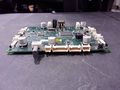
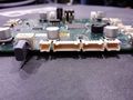
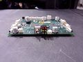
Images of Control Board
Back
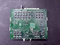
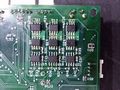
Motor FETs
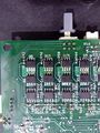
Motor FETs
Single Motor Circuit
Motor FETs
Motor FETs
System Clock
Top
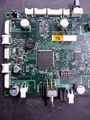
Top
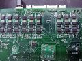
Connectors
Connectors
Power Switch
Connectors
Left View
Right View
Connectors
Kicker Discharge Button
Robot ID Select
Robot ID Select
Left Angled View
Side View
Status LEDs
Power Switch
Encoder & Kicker Connectors
Motor & Encoder Connectors
Power Inductor
Kicker Power Connector
Power Circuits
Selectable Switches
Xilinx FPGA
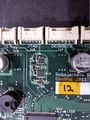
Board ID Location
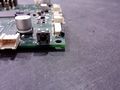
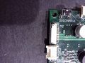
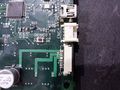
USB Connection
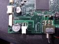
Atmel Microcontroller
Accelerator/Gyroscope Sensors
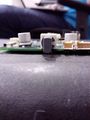
Reset Button
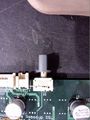
USB & Antenna Connections


Board Overview Videos
| Board Overview | |
| FPGA |