Difference between revisions of "RC08HW1"
m (recategorizing) |
Kberzinch3 (talk | contribs) m (Text replacement - "Category: Year: 2007-2008" to "Category:2007-2008") |
||
| Line 36: | Line 36: | ||
[[Category: RoboCup]] | [[Category: RoboCup]] | ||
[[Category: Electrical]] | [[Category: Electrical]] | ||
| − | [[Category | + | [[Category:2007-2008]] |
Revision as of 21:56, 18 July 2018
Contents
Video Version
http://www.youtube.com/playlist?list=PL81CC6DA215412DD0
Getting Started
Before we begin the real work here are few things to get everyone up and running with our tools. By the end of this mini-tutorial you should be:
- Able to work with Eagle CAD and have it installed on your home machine
- Able to edit and post material to the wiki
Part One: Playin with Eagle
Eagle CAD is a fairly decent, free, electical CAD software that gives you the ability to draw schematics and then build actual board layouts from these schematics. Once you have built a schematic and layout in Eagle you can then send off the files describing the board to your favorite fab house like Advanced Circuits. We are moving towards using Eagle as our standard CAD software, therefore in order to electrical design with us you are going to need to learn Eagle CAD. Now, I could have written this tutorial myself but I'm lazy. So, I'm going to use the tutorial from Sparkfun. (If you don't know already, Sparkfun is the online retailer for all things embedded. If you have a devious project in mind Sparkfun is the place to start.)
The tutorials on Sparkfun cover all aspects of embedded design and I'd advise reading them, but for our purposes you should look at the lecture 8 and lecture 9. In these two tutorials you are going to be using the Sparkfun Eagle library which you can download here. When you finish the tutorials you are going to want to show of your creation to the world by way of our wiki. The process for doing that is handled in part two.
Part Two: Postin Stuff to the Wiki
By now, if you don't already, you need to sign up the wiki. Its really easy to due just click the log in/create account link at the top of this page. There you will be asked to give a nickname, password, e-mail, and the answers to some simple math. (No complex integrals yet...) When you have done that e-mail Andy (RoboCup leader) or Stefan (PR chair) that you would like to be added to the wiki. In the mean time you should be able to edit pages once you have created an account.
On this page everyone should paste a screenshot of their layout in Eagle and the schematic files. To do so you need to click on the edit tab at the top of this page and place a tag for your image using the syntax [[Image:Example.jpg]]. When you have done that click on who preview. Where you have place the image tag should be red or broken link. Click on that link and open it in a new tab (don't open it in the current window you will lose your changes to the page) upload your file, come back the tab with this page and click save and you should see your artwork on this page. If you need help theres a help link under navigation on sidebar. You should do the same for the schematic.
Now that you have completed the tutorial here, go out and celebrate!
Post your Layouts and Schematics Here
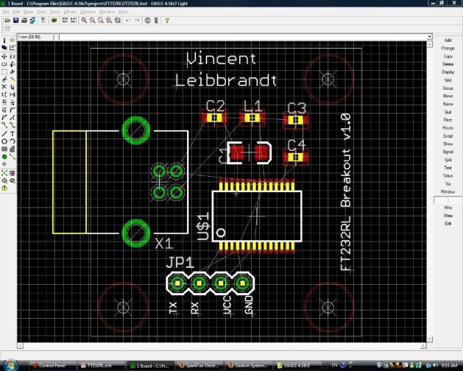
This is how far I got on the tutorial. I stopped right before the sparkfun tutorial went on to discuss gerber files in lecture 9. As a side note, my 4 pin connector is connected wrong for some reason and there are other mistakes scattered about. Its obviously not very efficient either. However, I am now fairly familiar with the techniques used up to this point.
-Vincent Leibbrandt
OK...I've read through the tutorials and have fiddled around with Eagle...getting comfortable with it. Didn't make/post the entire layout from the CAD [kudos, Vincent, by the way], but think I have a pretty good feel for the program.
