Difference between revisions of "RC08Brushless"
(→Articles) |
(→Motor Controller Chip) |
||
| Line 23: | Line 23: | ||
====Motor Controller Chip==== | ====Motor Controller Chip==== | ||
* '''Using an FPGA instead of a DSC''' | * '''Using an FPGA instead of a DSC''' | ||
| − | |||
| − | |||
| − | |||
| − | |||
| − | |||
| − | |||
| − | |||
| − | |||
| − | |||
| − | |||
* [[RC08BLDCMotorDrivers | Matrix of Potential Drivers]] | * [[RC08BLDCMotorDrivers | Matrix of Potential Drivers]] | ||
Revision as of 19:36, 9 April 2008
In 2008 RoboCup switched to brushless DC motors. While brushless motors are smaller and far more efficient than brushed motors the commutation normally performed inside a brushed DC motor will need to be done externally using some control circuitry. There are two main parts to our brushless motor controller solution; the controller which uses sensors on the motor to gate signals to one of three coils, and the half-bridge motor drivers which actually drive the coils.For the controller a special-purpose brushless motor driver IC was used. For information on the motors or motor control software please see their respective pages.
Contents
Tasks
- [ ] Get the motor and begin playing with it
- [X] Call Maxon and get a recommendation on motor drivers (Note: Already have design for motor drivers)
- [X] Figure out max current draw. (10A starting current)
- [X] Develop Model of Motor and get Frequency Response (Note: This is a task to be covered in firmware)
- [X] Find and purchase Flat Flex Cable (FFC) connectors (Note: Found one)
- [X] Purchase large mosfets for testing (Note: Test rig built and verified with drive motors)
- [X] Purchase Surfboard for mounting DSC
- [X] Build test rig
- [X] Finalize on a DSC (Note: No DSC this year. Doing it in logic)
- [X] Choose MOSFETS
- [X] Sample all the parts
- [X] Schematic Design
- [ ] Build prototype
- [ ] Prototype evaluation
- [ ] Verify current draw under load especially start-up
- [ ] Check if there is any temp rise in FETs in continuous operation
- [ ] Make necessary changes
Specifications
Motor Controller Chip
- Using an FPGA instead of a DSC
- Matrix of Potential Drivers
MOSFET
- See below for the parts to be used this year
- NMOS and a PMOS
- The FETS have to be able to handle 10A on current
- Matrix of Potential FETS Other FETs we considered
Schematics
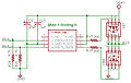
Brushless Motor Driver Schematic

Parts
We are performing commutation on the FPGA with gate drivers.
Gate Driver
Microchip TC4428
- 1.5 A
- 6 mA quiescent
- Noninverting low side
- Inverting high side
FETS
| Part No. | Make | Package | ContIDS | MaxIDS | Rds | MaxVGS | Samples | Data Sheet |
|---|---|---|---|---|---|---|---|---|
| NTMS4503N N-Channel | ON Semi | SO-8 | 14 A | -- | -- | 28 V | Y | [1] |
| NTMS10P02 P-Channel | ON Semi | SO-8 | 10 A | -- | -- | 20 V | Y | [2] |
Motor Connector
Hirose FH12-11S-1SH 11 position 1 mm pitch
Commutation
CW (looking along the shaft toward the motor)
| HS 1 | HS 2 | HS 3 | Winding 1 | Winding 2 | Winding 3 |
| 1 | 0 | 1 | Vcc | Gnd | n.c. |
| 1 | 0 | 0 | Vcc | n.c. | Gnd |
| 1 | 1 | 0 | n.c | Vcc | Gnd |
| 0 | 1 | 0 | Gnd | Vcc | n.c. |
| 0 | 1 | 1 | Gnd | n.c. | Vcc |
| 0 | 0 | 1 | n.c. | Gnd | Vcc |
CCW (looking along the shaft toward the motor)
| HS 1 | HS 2 | HS 3 | Winding 1 | Winding 2 | Winding 3 |
| 1 | 0 | 1 | Gnd | Vcc | n.c. |
| 1 | 0 | 0 | Gnd | n.c. | Vcc |
| 1 | 1 | 0 | n.c | Gnd | Vcc |
| 0 | 1 | 0 | Vcc | Gnd | n.c. |
| 0 | 1 | 1 | Vcc | n.c. | Gnd |
| 0 | 0 | 1 | n.c. | Vcc | Gnd |
To find this data:
- Go to https://support.maxonmotor.com/
- Guest Login
- Search for commutation sequence
- First link is "Block Commutation Sequence of maxon EC motors"
I duplicated the tables here because the text on the site is generated by Javascript, the frame URL contains a session ID, and the back button doesn't work.
Articles
Links
- Electrical System
- Motor Datasheet: Media:07_197_e.pdf