Difference between revisions of "RC08Brushless"
(→Parts) |
(→Schematics) |
||
| Line 40: | Line 40: | ||
==Schematics== | ==Schematics== | ||
| − | + | <gallery> | |
| + | Image:RC_mot_drvr_08.jpg|Brushless Motor Driver Schematic | ||
| + | </gallery> | ||
| + | |||
==Parts== | ==Parts== | ||
We are performing commutation on the FPGA with gate drivers. | We are performing commutation on the FPGA with gate drivers. | ||
Revision as of 12:44, 23 January 2008
In 2008 RoboCup switched to brushless DC motors. While brushless motors are smaller and far more efficient than brushed motors the commutation normally performed inside a brushed DC motor will need to be done externally using some control circuitry. There are two main parts to our brushless motor controller solution; the controller which uses sensors on the motor to gate signals to one of three coils, and the half-bridge motor drivers which actually drive the coils.For the controller a special-purpose brushless motor driver IC was used. For information on the motors or motor control software please see their respective pages.
Contents
Motor Frequency Analysis
Tasks
- [ ] Get the motor and begin playing with it
- [X] Call Maxon and get a recommendation on motor drivers (They spec parts not sure which drivers they use)
- [X] Figure out max current draw. (10A starting current)
- [ ] Develope Model of Motor and get Frequency Response
- [ ] Find and purchase Flat Flex Cable (FFC) connectors
- [ ] Purchase large mosfets for testing
- [ ] Purchase Surfboard for mounting DSC
- [ ] Build test rig
- [ ] Finalize on a DSC
- [ ] Choose MOSFETS
- [ ] Sample all the parts
- [ ] Schematic Design
- [ ] Build prototype
- [ ] Prototype evaluation
- [ ] Make necessary changes
Specifications
Motor Controller Chip
- The motor is spec'd at 12V and is 30W
- A decent transient response (dead-time + switching time)
- 3-Channels in one package
- Braking is not a requirement but would be nice
- High Impedance OFF state
- Fault protection (overvoltage, overcurrent, fast response)
- Small package
- Ability to operate in the >20kHz range
- Gate drive capability (either can directly driver the gate or is open drain.)
- Data sheet recommends a MOSFET
- Matrix of Potential Drivers
MOSFET
- NMOS and a PMOS
- The FETS have to be able to handle 10A drain current
- Matrix of Potential FETS Other FETs we considered
Schematics
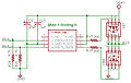
Brushless Motor Driver Schematic

Parts
We are performing commutation on the FPGA with gate drivers.
Gate Driver
Microchip TC4428
- 1.5 A
- 6 mA quiescent
- Noninverting low side
- Inverting high side
FETS
| Part No. | Make | Package | ContIDS | MaxIDS | Rds | MaxVGS | Samples | Data Sheet |
|---|---|---|---|---|---|---|---|---|
| NTMS4503N N-Channel | ON Semi | SO-8 | 14 A | -- | -- | 28 V | Y | [1] |
| NTMS10P02 P-Channel | ON Semi | SO-8 | 10 A | -- | -- | 20 V | Y | [2] |
Motor Connector
Hirose FH12-11S-1SH 11 position 1 mm pitch
Articles
Modeling a DC motor Brush-Less Motor Simulink
Links
- Electrical System
- Motor Datasheet: Media:07_197_e.pdf