Electronics Basics
Contents
Overview
Electronics are an important consideration of all Combat bots. Robots without strong electronics can suffer from shorts and over-voltage, which can ruin components and disable the robot. Creating a strong electrical system is crucial to increasing the durability and maximizing the damage output of the robot. Additionally, compact electronics allow the designer to decrease the size and footprint of the robot, making it a harder target and allowing more weight to be distributed to the armor and weapons.This guide will offer a detailed explanation of the components used in a combat robot's electronics and describe how to assemble the components into a strong and small circuit.
3lb Circuit
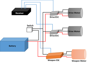
The standard 3lb electrical layout consists of a 1000 mAh 11.1 V battery connected to a mechanical switch, which powers 2 drive ESCs and a Weapon ESC. The ESCs are each connected to a receiver and send power to the motors in 3 phases.
Parts List
| Component | Size | Weight |
|---|---|---|
| DYS BE1806 2300KV (Drive Motor) | 0.91x0.91x0.83in | 0.053 lbs |
| DYS BL20A Mini 20A BLHeli ESC OPTO (Drive ESC) | 0.91x0.47x0.18in | 0.017 lbs |
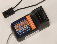
| HobbyKing 2.4Ghz 6Ch V2 (Receiver) | 1.75x0.53x0.88in | 0.029 lbs |
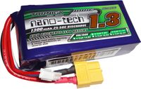
| Turnigy nano-tech 1000mah 3S 45~90C Lipo Pack (Battery) | 2.80x1.38x0.75in | 0.21 lbs |
Motors
Overview
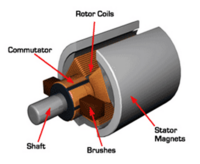
Motors consist of a rotor (rotating part) and a stator (stationary part). The rotor is made up of an armature that drives the load which is surrounded by magnets and supported by a bearing to reduce friction. The stator is made up of a core surrounded by coils of wire connected to a power source that is used to drive the motor. The stator has a core made up of laminated sheets of metal to reduce energy losses. A commutator is also included in brushed motors to flip the magnetic field as the motor spins.
Brushed vs Brushless
Brushed motors operate by sending current through coils of wire to induce a magnetic field and cause the motor’s permanent magnets to turn. Once the magnets have spun 180°, the current is reversed using a communicator, and the magnets continue to spin another 180° and the process repeats. Brushed motors are more durable than brushless motors, but suffer from less control and slower speeds than brushless motors.
Brushless motors operate using three phase AC current generated by a switching power source or an ESC. The 3 phases of the current are 120 defrees out of phase, meaning that when one line has no current, the other lines have a current at plus and minus cos(120°). These wires are connected in loops around the motor in alternating phases so that at any moment, one wire is pushing the motor forward, one is pulling the motor forward, and the last has no current.
Brushless motor’s have a higher power to weight ratio and higher speed than brushed motors. Battlebots uses brushless motors for its robots due to the control and speeds that they posses. Note that the direction of the motor can be reversed by switching any 2 of the wires.
Inrunner vs Outrunner
Inrunner motors have the permanent magnet rotor inside a ring of electromagnets with the armature connected directly to the rotor. Inrunner motor’s have high rpm and are more efficient than outrunners, but have less torque and weigh more.
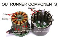
Outrunner motor’s have the permanent magnet rotor outside a core of electromagnets with the armature connected to a plate on the back of the rotor. Outrunner motors provide more torque than inrunners, but suffer from less rpm and a spinning body that can be constricted by wires.
Choosing a Motor
When choosing a motor there are several parameters that need to be considered to make an informed decision. These values will affect the speed and power output by the motor and will affect how hard your weapon hits, how long it takes to spin up, and could change how your robot drives. These are the constants you should be familiar with when you look for a motor.
Kv: How fast the motor spins per Volt supplied to it. A 1000 Kv motor will spin at 1110 rpm when supplied with 11.1 V. Note this is the unloaded speed and will be lower when your weapon is attached. Kv is inversely related to torque, which relates
Weight: Weight is an important consideration when choosing a motor. You may be tempted to choose the fastest and most powerful motor for your robot, however larger motors will quickly burn through your available weight and require you to use bigger and heavier ESCs.
Max Current: The max current will determine the ESC that you need to control the motor. Your ESC should be at least as large as the max current the motor can draw. Typically motors with a max current of 40 A or less are used to keep the ESC small and light. The size of the ESC tends to increase significantly at 50 A.
ESCs
Overview
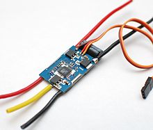
An ESC (Electronic Speed Control) receives a control signal from the receiver that dictates how much power to output to the motor. It then generates a signal of the proper power and sends it to the motor. For brushless motors the ESC will generate a three phase AC signal, and for brushed motors the ESC will generate a constant signal. Click here to learn more about the difference between brushed and brushless ESCs. The ESCs adjust the phase of the output based on the motor rotation, which it measures using the back emf response from the motor. This allows the user to spin the motor at different speeds to control the speed and direction of the robot
Choosing an ESC
ESCs are chosen based on the max current they will experience. Generally the ESC’s rated current should be higher than the motor’s rated current. For example a 30A motor will generally require a 40 A ESC to prevent overvoltage. The ESCs will also need a Battery Eliminator Circuit (BEC) to step down the voltage sent to the receiver. The presence of a BEC will be listed in the ESC’s product specifications.
Batteries
Battlebots uses Lithium Polymer batteries to power our electronics. Lithium polymer batteries are compact rechargeable batteries made using a polymer electrolyte to reduce weight. LiPo batteries have high energy density and low weight, making them perfect for applications with weight restrictions. When selecting a battery, it is important to consider the voltage and capacity. The voltage is the level necessary to power the circuit and must be calculated using the power consumption of the components. The capacity will tell you how long the battery will run and is measured in milliamp hours. The 3lb robots use a 11.1V 1000mAh 3-cell battery which has enough charge to power the robots for their three minute matches.
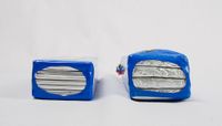
Safety: LiPo batteries can be very dangerous if mishandled or punctured, therefore you should be careful when handling charged or charging batteries. Also remember that a battle bot with a battery plugged in should be treated as powered on with a live weapon. Below are some guidelines on how to safely handle and use LiPo batteries.
1. Never use a damaged battery. If you believe that your battery is damaged, bury it in a bucket of sand. The sand bucket at the SCC is the metal bucket outside the office. At competition, the officials will tell you where the bucket is at the drivers meeting. A damaged battery will puff up and/or keep heating heat up after unplugged. If a battery is visibly expanding, there is an extreme risk of exploding and it should be buried in sand ASAP.
2. Use the balancing board when charging. If the voltage of the cells in the battery become unbalanced, it could become unstable and explode.
3. Store batteries in a fireproof bag. Overcharged or damaged batteries can spontaneously catch fire, and should be stored properly to be safe.
4. Never overcharge or use an overcharged a battery. Our chargers should automatically stop when the battery is full, but the voltage should never exceed 4.2 V per cell.
5. Store batteries at room temperature. Hot temperatures can melt the battery and cold temperatures may result in condensation inside the battery, which can result in shorts and fires.
6. Never use an undercharged battery. Batteries last around 300 charges, throw out the battery when the voltage is below 3 V per cell.
Receiver
Overview
The controllers that you will use contain a transmitter which broadcasts a control signal to the receiver on the robot. The receiver decodes the signal and transmits instructions through different channels that connect to each component in the circuit. These signals tell the ESCs how much power to route to each motor which allows the user to control the robot from a distance.
The receivers that Battlebots uses have six channels, but we only use three of them to control the robot. The first channel is connected to the weapon ESC which controls how fast the weapon spins. The control stick connected to this channel has a fixed position, which is useful for keeping a constant power to the motor. The next two channels connect to each drive ESC and are used to maneuver the robot. The drive stick uses the vertical position of the stick to control the power sent to both motors and the horizontal position to send more power to one motor when executing a turn. The final channel that is present in all newer receivers is the binding channel. This channel is used to bind the transmitter in the controller directly to the receiver int the robot. This step only needs to be completed once and lasts until the receiver is re-bound to a different transmitter. Note that when binding the receiver, the trim of the controller might need to be adjusted for the receiver to detect all channels. Trim are knobs that finely tune how much power is transmitted when the stick is pushed a specific amount. These will need to be adjusted if the robot lists to one side when driven forward.
How to Bind
Below is a step by step guide on how to bind your receiver to the transmitter on your controller.
1. I don't know how to do this yet.
2.
3.
Manufacturing
Wire Selection
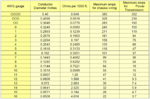
When wiring your circuit together, you need to choose wires with a large enough diameter that they can conduct the current flowing through them without melting. However you also want wires that are thin enough to fit into the empty space inside your robot. Wires are graded by their gauge or thickness, with larger diameter correlating with a smaller gauge. To find the minimum gauge wires needed to effectively power the components, you can consult an ampacity chart. The ampacity of the wires should exceed the maximum rating of your ESCs.
Soldering
Connectors
Insulation
Once you've soldered your components to their respective wires, you will need to insulate them to prevent the exposed connections from grounding to your robot's chassis. Generally this is done by wrapping the component in heat shrink. Heat shrink is a material that, as the name suggests, shrinks as heat is applied to it. Simply thread a pre-cut piece around the component, then use a heat gun to shrink it until it is wrapped firmly around the part. Additionally, if heat shrink is unavailable or time is of the essence, you may simply wrap electrical tape around the joint to protect it. For extra insulation, it is recommended that you coat your metal plates in an an insulating substance, like spray paint, to further prevent your electronics from grounding to the chassis.
