Difference between revisions of "Data Acquisition"
(→Wheel Encoders) |
(→Wheel Encoders) |
||
| Line 33: | Line 33: | ||
===Wheel Encoders=== | ===Wheel Encoders=== | ||
| − | We may be able to connect the encoder to the back of the motor instead of near the wheel. There is a recessed shaft (under a cover) at the back of the motor that is hexagonal (~0.79" diameter). It isn't long enough (< 0.25" I think) so the encoder can fit directly around it, but there may be a way to connect a rod inside of it -- there is a 0.385" hole in the shaft (that has something in it now) and a set screw (pin, really) | + | We may be able to connect the encoder to the back of the motor instead of near the wheel. There is a recessed shaft (under a cover) at the back of the motor that is hexagonal (~0.79" diameter). It isn't long enough (< 0.25" I think) so the encoder can fit directly around it, but there may be a way to connect a rod inside of it -- there is a 0.385" hole in the shaft (that has something in it now) and a set screw (pin, really) holding it in which goes all the way through the shaft. I haven't been able to take this apart yet. As for mounting, there are four screw holes (size 8-32) equally spaced around the outside of the motor (~3.5" apart longways) and two recessed screw holes (size 8-32) inline with the outer holes (~2.7" apart longways). The inner holes don't have very much clearance to the motor wall near the outside (~0.15"). |
<br style="clear:both" /> | <br style="clear:both" /> | ||
Revision as of 11:16, 28 September 2007
Contents
Mission
Abstracting hardware sensors into quality data that can be accessed over a software interface
Sensors
GPS
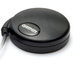
For our first semester prototype, Alex selected the: Garmin GPS 18 5Hz ($200)
- Updates every 200ms
- Accurate to at least 3.5m, expected accuracy of ~1m
- 12 parallel satellite tracking, WAAS enabled
- Does not require a subscription to any service
- Voltage Requirement: 4.0-5.5V
Gyro and Accelerometer
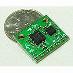
The gyro and accelerometer are a combo system created by SparkFun. It incorporates both the ADXL330 and IDG300 to enable measurements of acceleration along the x, y, and z axes and of angular rate about the x and y axes. For more information, please visit SparkFun's page on the IMU 5 Degrees of Freedom.
- IMU 5 Degrees of Freedom
- Voltage Requirement: 3.3V
Compass
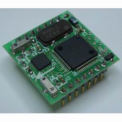
- PNI Vector 2Xe Compass Module
- SPI Interface
- Accuracy: Max: 2° RMS; Typical: 1° RMS
- Power Requirement: 2mA @ 3.3V
Wheel Encoders
We may be able to connect the encoder to the back of the motor instead of near the wheel. There is a recessed shaft (under a cover) at the back of the motor that is hexagonal (~0.79" diameter). It isn't long enough (< 0.25" I think) so the encoder can fit directly around it, but there may be a way to connect a rod inside of it -- there is a 0.385" hole in the shaft (that has something in it now) and a set screw (pin, really) holding it in which goes all the way through the shaft. I haven't been able to take this apart yet. As for mounting, there are four screw holes (size 8-32) equally spaced around the outside of the motor (~3.5" apart longways) and two recessed screw holes (size 8-32) inline with the outer holes (~2.7" apart longways). The inner holes don't have very much clearance to the motor wall near the outside (~0.15").
Laser Range Finder
Current LIDAR: Hokuyo URG-04LX
- Indoor model, not suitable to our needs
Next Semester LIDAR: SICK LMS
- Currently hoping to borrow one of these units from the Urban DARPA project
- Outdoor model, used by all serious competitors


