Difference between revisions of "Maori Design Guide"
(→Introduction) |
(→Design Decisions) |
||
| Line 100: | Line 100: | ||
The hubs used to constrain the beater bar were made of Aluminum 6061-T6. These parts were machined in house, so ease of machining outweighed high-strength material selection. However, the brunt of forces are received by the beater bar and chassis, meaning high-strength material was not necessary, and in fact benefits the design. This material selection allows deformation of the hubs before the beater bar and chassis (which were more complex parts and thus harder to machine). The hubs interface with the beater bar using a fork-shaped puzzle fit, which constrains axial and radial motion. A dual belt slot was machined into one of the hubs to interface with the weapon motor. Using two belts effectively halves the load on the belts and allows a "built-in" backup belt in the event one is torn by an opponent. The hubs, similarly to the the beater bar, are rotationally symmetric for 180 degrees to avoid skewing the center of mass of the weapon assembly. | The hubs used to constrain the beater bar were made of Aluminum 6061-T6. These parts were machined in house, so ease of machining outweighed high-strength material selection. However, the brunt of forces are received by the beater bar and chassis, meaning high-strength material was not necessary, and in fact benefits the design. This material selection allows deformation of the hubs before the beater bar and chassis (which were more complex parts and thus harder to machine). The hubs interface with the beater bar using a fork-shaped puzzle fit, which constrains axial and radial motion. A dual belt slot was machined into one of the hubs to interface with the weapon motor. Using two belts effectively halves the load on the belts and allows a "built-in" backup belt in the event one is torn by an opponent. The hubs, similarly to the the beater bar, are rotationally symmetric for 180 degrees to avoid skewing the center of mass of the weapon assembly. | ||
| − | The tensioning system for the weapon pulley relied on a bar with two small bearings to press down on both of the | + | The tensioning system for the weapon pulley relied on a bar with two small bearings to press down on both of the belts (as pictured to the right). When assembled, the plates bent inward so that they were no longer parallel. One solution to this problem would be putting slots in the top and bottom plates into which the pulley plates would fit. |
The section view of the weapon assembly shows how steel "pins" were bolted into the side plates of the chassis, allowing the bearings which were press-fit into the hubs to have a dead shaft to sit on. | The section view of the weapon assembly shows how steel "pins" were bolted into the side plates of the chassis, allowing the bearings which were press-fit into the hubs to have a dead shaft to sit on. | ||
Revision as of 18:13, 25 April 2020
Introduction
YO. It's the journey, not the destination. We ate CRABS, we pitched it to Dwayne "The Rock" Johnson, and we didn't get rona. This baby is ready for a fight, but she just has to wait.
This is MAORI BABYYYYYYYYYYYYYYYYYYYYYYYYY
Members:
Bot Lead: Thomas Jackson, Prawn Prince
Bot Mentor: Nico Castro, King Crab
The Bs: Lil, and Big (Brain Epstein and Brian Hales)
The Crispi Kids: Damian, Alex, Brenden
Honorary Members: Ava, Dennis, Hank the Tank
Design Basics
Chassis
Overview
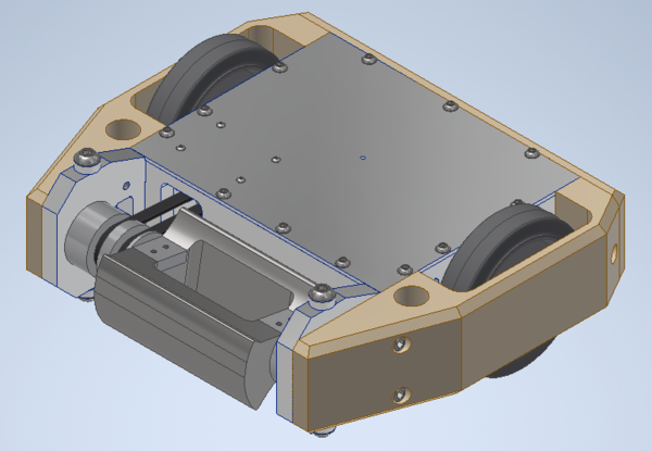
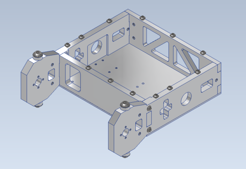
Maori's chassis consists of six parts: A top, bottom, front, and back plate as well as two side plates. All of these components are made from 6061 Aluminum. The side plates provide thicker support towards the weapon, while allowing skids to be inserted. Maori's drive modules also fit into the side plates. The front plate allows for belt access between the interior of the robot and the weapon pulley. It also fits into the side plates. The bottom and top plates provide slots for interior plastic guards and bolt into the rest of the chassis.
Design Decisions
Overall, the chassis of our drum type spinner robots have always focused on durability and survivability. We use thicker aluminum plates that slot into each other, along with steel bolts to ensure the base structure of our robot is strong. No real surprises here.
Side Plates (0.5"): Slightly thicker towards the front, along with a slightly flared and rounded profile. Drum spinners run the risk of being ripped open by other robots if the interface between the weapon and chassis is not well put together. To account for this, the front of Maori is a bit thicker than the rest of the side plate (0.625" vs 0.5"). The roundedness to the head/lack of corners is to reduce the number of places where a horizontal spinner would be able to get a good hit on that support portion of the side plates. Cut-outs on the side plates allow for access to the tensioning system for the belt once the armor is removed. The side plates also have weight saving cut outs, and slight pockets that let the drive modules slot in nicely.
Front Plate (0.5"): Standard plate with a cut-out for the belt. Pocketing here gives a bit more room for electronics, while still providing structural support. Slots into side plates.
Back Plate (0.375"): Slightly thinner than the rest of the main chassis plates, but has general weight saving cut-outs. The general idea is that this plate will be slightly thinner as it should not be hit extensively during a fight. Armor also helps with this.
Top/Bottom Plate (0.125"): Maybe slightly too thin, but seemed to hold up well during assembly and testing. Provides holes that allow the tensioning system to bolt into something, while also providing some slots for internal plastic guards.
- Notes/Helpful Advice
- In the end, due to the fact that our weapon did not have its central cut-out made, the back plate was made out of steel to counter balance the front loaded weight. It was not test driven with this new addition, but this has worked in the past.
Armor
Overview
Maori's armor is composed of three HDPE components. This consists of two side armor blocks and a plate mounted to the back.
Design Decisions
The design behind the armor was striving to make the robot profile a bit rounded. The armor is fairly thick (0.5"-2.25") HDPE. The armor in this case wraps around the wheels. This is over the choice to have another side plate what would protect the wheels. The success of this choice hasn't been tested yet, but at least we believed that the thinner section of the HDPE around the wheels would be able to protect them. Apart from the weight saving cuts, this armor acts as our usual thick HDPE armor does.
- Notes/Helpful Advice
- These parts were made with the waterjet, and resulted in a large amount of floating plastic that was tough to clean. Overall though, waterjetting worked, and the holes that would be made to fasten the armor to the robot were then just simply made on the mill.
Drive
Overview
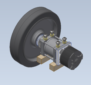
The drive assembly is a robust one: An outrunner motor adapted to fit into a Bane Bots gearbox. A multi-piece hub and spacer set, along with a bearing pressed into the side plate allow for proper function.
Design Decisions
Wheels: Performa Wheels (5") are always a good pick due to their solid build and great traction. The hubs that came with the wheels were pressed out for our own custom hubs.
Wheel Hubs: Made of aluminum, these hubs key into the wheel. The hub then keys into the shaft of the gearbox, allowing for rotational transmission. In terms of transverse constraints, the inner bore of the gearbox shaft is threaded. Because of this, we were able to make the head of the hub a separate piece that bolts on to keep the wheel in place against a tiered spacer.
Gearbox: Its specifications can be found in the electronics section. In terms of mechanics, the specific gearbox back plate topology was chosen to allow the motor to bolt on. The gearbox also has bolt holes that allow it to be mounted to the bottom plate, and allow the 3D-printed cover to be mounted. A blank pinion gear was ordered and machined in order to properly interface the added motor and gearbox on the inside.
Motor: Its specifications can be found in the electronics section.
3D-printed Cover: A simple enclosure that houses the drive system. Allowed for wires to be routed over and around the drive system.
Calculations and Testing
Calculations made for the drive can be found here: https://docs.google.com/spreadsheets/d/1scdVNzY6Q3a9BCemg0K2he29hvwmrmOmIFCIPTrqUPA/edit?usp=sharing It's evident that the final numbers here are off. Investigation needs to be done to find the cause, but if using this to compare motors, it should do the job fine.
We prioritized speed over torque, but in reality the speed could be lower since during testing we didn't even get to try top speed and had a few issues with control. The robot is able to push the anvil and a stock bar on the shop floor, so it can push a weight of 60 pounds roughly. When pulling this with the spring scale in the shop (unsure if it is accurate or in the right units) the max push force of Maori is roughly 15 lbs. Maori's motors did not stall during this process though, instead the wheels were skidding.
- Notes/Helpful Advice
- Nothing too fancy here with the drive system. We were originally unsure on how to approach the drive system originally, but found a helpful video made by Robert Cowan on his robot Crippling Depression. The techniques he uses to make his drive system are very similar to the ones we used for Maori. Watch his series of videos for a good primer on 30lbers.
Weapon
Overview
Maori's weapon system consists of a steel drum to cause damage to opponents and two aluminum hubs to interface the weapon with the chassis. The drum is constrained to the hubs with bolts perpendicular to the axis of rotation to minimize loosening caused by vibration. The fork shape of the hubs compromises ease of machining with functionality.
Design Decisions
The material used for the beater bar was S7 Tool Steel. In practice, this material is a good fit for the weapon, as it can be machined fairly easily to start with, and can then be heat treated for an immense increase in strength. S7 tool steel is the go to material for big bot weapons. While designing the beater bar, compatibility with EDM (electron-discharge machining) was prioritized. The beater bar was given a constant cross-section along the axis of rotation to help in this regard. The profile of the beater bar is rotationally symmetric for 180 degrees to minimize vibration induced by an offset center of mass. Flats on each teeth were part of this profile to use for clamping when milling out the interior profile. The teeth of this profile were a significant issue during testing, as they reduced the "reach" of the weapon - the teeth were the same radius as the majority of the weapon, allowing objects to just bounce off of the weapon instead of getting damaged. This is a big issue for weapon designs in general. Make sure to have the tooth of the weapon be the only part of the profile that sticks out the farthest.
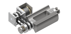
The hubs used to constrain the beater bar were made of Aluminum 6061-T6. These parts were machined in house, so ease of machining outweighed high-strength material selection. However, the brunt of forces are received by the beater bar and chassis, meaning high-strength material was not necessary, and in fact benefits the design. This material selection allows deformation of the hubs before the beater bar and chassis (which were more complex parts and thus harder to machine). The hubs interface with the beater bar using a fork-shaped puzzle fit, which constrains axial and radial motion. A dual belt slot was machined into one of the hubs to interface with the weapon motor. Using two belts effectively halves the load on the belts and allows a "built-in" backup belt in the event one is torn by an opponent. The hubs, similarly to the the beater bar, are rotationally symmetric for 180 degrees to avoid skewing the center of mass of the weapon assembly.
The tensioning system for the weapon pulley relied on a bar with two small bearings to press down on both of the belts (as pictured to the right). When assembled, the plates bent inward so that they were no longer parallel. One solution to this problem would be putting slots in the top and bottom plates into which the pulley plates would fit.
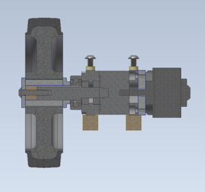
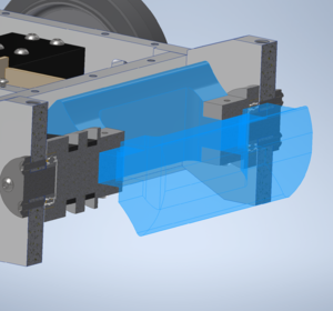
The section view of the weapon assembly shows how steel "pins" were bolted into the side plates of the chassis, allowing the bearings which were press-fit into the hubs to have a dead shaft to sit on.
Calculations
The weapon motor was chosen based on two different models. The first model was generated internally by RoboJackets and was of dubious accuracy. That model can be found here <insert link>. The second model was designed by Team Run Amok Combat Robotics and can be found here: http://runamok.tech/AskAaron/tools.html. This model was created in 2007 and has been reviewed and updated through 2017. One notable feature of the Run Amok model was the inclusion of the "soft start" feature included in most ESCs. The RJ model does not factor in this feature. The Team Run Amok model allows for inputs of weapon moment of inertia, motor type (brushed or brushless), internal motor stats (Voltage, Kv, Ri, poles, and gear reduction), match length, and number of spin ups. As outputs the model returns power required, weapon speed, tip speed, energy required, and elapsed time.
- Notes/Helpful Advice
- Make sure to review the RioBotz BattleBots Manual for insights on how to shape the weapon, how many teeth to have, and how much tooth bite your device will achieve. This is a key handbook so make sure to review this for good weapon design!
Electronics
Overview
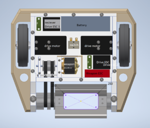
Maori uses a single battery that powers three parallel circuits, two of which are for drive. There are two 100 A fuses: one for the weapon, the other in series with the two drive circuits.
Here is a list of components:
- Turnigy 5000 mAh 6S 25C Lipo pack - Single batteries seem to work well with the amount of space in a 30lber. Other robots attempted to utilize two smaller batteries, but faced spacing and electrical issues. While it is not impossible, and even advantageous to use two batteries in series for more voltage, or parallel for more amperage, initially forays in this weight class may be more manageable with a design with a single battery. However, multi-battery systems should be refined and condensed for proper utilization.
- FrSky X8R 8-channel 2.4ghz reciever - This receiver is one that is compatible with the new big bot controllers recently purchased. Buy this reciever if you want to use the good controllers. They plug in like the old receivers, but are slightly larger.
- 2 Racerstar 120A ESC rated for 2-6S (drive ESCs) - More explanation below.
- Scorpion Tribunis 06-120A SBEC (weapon ESC) - Solid weapon ESC that pairs well with the selected weapon motor. Scorpion products are always high quality, and we get a discount from them as well. Lots of customization options with the software that accompanies it for programming. It takes a bit of time to get a handle off, but spin-up times can be adjusted with this programmable ESC.
- 2 Propdrive v2 4238 750KV brushless outrunner motor rated for 80A and 2-4S - More explanation below.
- Scorpion SII-4025-440KV - Solid weapon motor, anything from scorpion will be a good motor choice. We picked this motor for its sizing and KV/Current rating. Get yourself a scorpion motor today.
- 2 Blue Sea AMI/MIDI 100A fuses - In-line boat fuses. Fuses are always great for protecting your bots internals, and these are quite small and solder in-line, making them efficient current protection. This vendor is also great in general, you won't find fuses like these anywhere else.
- Team Whyachi MS-05 Switch - Big durable switch that can take the current our bot is working with. Use Team Whyachi switches for your big bots, they can handle the increased electrical needs.
Drive
The drive motors we went with were chosen for their theoretical performance discussed in the calculations portion of the Drive section. An interesting addition is that these motors were used in crippling depression, a very useful bot for learning about the 30lb weight class created by Robert Cowan. A solid go-to for our specific drive setup.
The Racerstar ESCs were the only reversible ESCs we could find for the required specs. In general, it seems that reversible ESCs on the market are build for weaker circuits. However, knowing the challenge and unreliability of buying airplane ESCs and reprogramming them, the Maori team decided to go with the reversible car escs.
Weapon
Nothing too much to discuss here. The motor connects normally with the circuit and is driven easily, as it bolts to a separate motor mount. Strong motor from scorpion -> hub -> double belts -> weapon hub = win.
- Notes/Helpful Advice
- Racerstar is sold by Banggood. This seller took 6 months for us to finally receive our ESCs, but they worked well. Its a toss up on when products from Banggood will arrive, so don't buy from them unless its a last resort.
- The racerstar ESCS, as far as we could find, are not programmable, so we could not adjust the specifics of how they work. This being said, these ESCs were the ones that got Mandiii 2nd at robogames. They are robust and can be fan cooled. Overall, a solid choice that has worked in the past, but could be improved on/optimized for future robots.
- The Scorpion ESC requires a lot of reprogramming. There is a software available on the scorpion website under the same page the esc was purchased. We were unable to finish getting the ESC to work optimally due to Covid-19 (dab). Out of the box, the motor and ESC have a spin-up of about 15-20 seconds which is unacceptable, but can easily be brought down to a 6 second spinup time with some quick tweaking. Obviously this needs be be brought down lower with more study of the software.
