Difference between revisions of "Mandiv Design Guide"
(→Gearbox) |
(→Gearbox) |
||
| Line 84: | Line 84: | ||
==== Differences from Mandiii ==== | ==== Differences from Mandiii ==== | ||
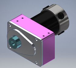
| − | [[File:Mandiv Full gearbox.JPG|right|thumb| | + | [[File:Mandiv Full gearbox.JPG|right|thumb|250px|Gearbox CAD]] |
The gearbox Mandiii used was just a compound gear train whereas the one Mandiv is using is a reverse compound gear train. This decision was made because we wanted to decrease the overall footprint of the gearbox within the robot. | The gearbox Mandiii used was just a compound gear train whereas the one Mandiv is using is a reverse compound gear train. This decision was made because we wanted to decrease the overall footprint of the gearbox within the robot. | ||
Revision as of 17:36, 12 November 2018
Contents
Introduction
Welcome to the Mandiv Design Guide! Mandiv is the fourth iteration of a 120 pound drum spinner created by RoboJackets. The purpose of this guide is to explain all of the reasoning behind the design decisions during the creation of Mandiv. This guide will go in depth on why certain designs were chosen as well as explaining some of the calculations used to support those decisions.
Design Basics
Chassis
Overview
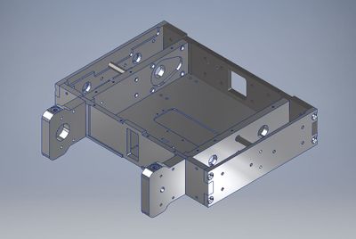
The chassis of Mandiv consists of eight parts: the left and right inner side plates, left and right outer side plates, front plate, back plate, top plate, and bottom plate. These eight plates are the frame of the robot and are what hold the entire robot together.
Design Decisions
We designed the different pieces of the chassis to puzzle fit together. This was because puzzle fitting allows for stronger connections between plates as well as providing easier assembly due to each plate being able to fit in place without screws being needed to hold it there. Screws were then used to attach each plate to one another, ensuring the whole chassis remains intact.
Each plate was pocketed in certain areas in order to reduce the overall weight of the chassis, to allow for some other parts to be inset in the chassis, and to provide some extra clearance between the chassis and other parts of the robot.
Differences from Mandiii
The main differences between Mandiv's chassis and Mandiii's chassis are the overall length and width of the robot, the thicknesses of the front and back plates, a standoff is used to support the middle of the outer side plate instead of an aluminum plate, and the pocketing of the outer side plates.
The overall length and width of Mandiv was design to be shorter than that of Mandiii in order to reduce the overall profile of the robot.
The thicknesses of the front and back plates were increased so that a larger screw could be used to attach the outer side plates.
We decided to use a standoff instead of an aluminum plate because the plate effectively acted like a standoff and using a standoff reduced overall machining time.
The pocketing on the outer side plates was changed due reduce the risk of those plates bending, which was a problem at competition for Mandiii.
Notes/Helpful Advice
The water jet's tolerancing isn't perfect, so when designing puzzle fits, add a tolerance of around 0.007 inches to both sides in order to ensure that the pieces fit together easily. This will save a good amount of time because you won't need to file the pieces to make them fit together.
Drum Assembly
Overview
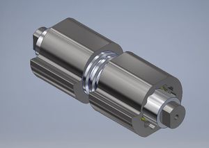
The drum is Mandiv's only weapon and is what's used to cause damage to opposing robots. Mandiv's drum assembly is made up of two separate drum halves, which are connected with a pulley in the middle. The drum halves are constrained to the pulley via a spline and a force pushing the drums on the spline cause by tightening screws from the inner side plates into the drum shaft.
Design Decisions
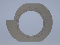
We decided to make the overall shape of the drum using a spline instead of just a typical circle with a tooth coming out of it. This decision was made because it significantly increased the moment of inertia for the drum. It also allowed for us to have a bigger tooth (more reach) than if we had just a circle with a tooth.
We decided to put the pulley between the two drum halves instead of on one of the sides in order to protect it a little more. This is because when the pulley is on the side, it is more exposed to taking hits from other robots (especially horizontal bar spinners). The thought process of moving it to between the drums is that it would no longer be exposed to hits from the sides, and that other robots would hit our drum before hitting the pulley.
A spline was used to attach the drums to the pulley because it was calculated that the spline provides the strongest shear strength and safety margin of the methods we tested. The diameter of the weapon shaft was increased in order to reduce the chance of bending (hopefully eliminate the chance of it).
The flats were added onto the drum to provide an area to clamp the drum in order to make machining it easier.
Calculations
The shaft bending calculator takes in the dimensions as well as the amount of bending that occurred on that shaft in order to calculate the necessary force required to bend that shaft by that amount. It then calculates the safety margin for the shaft for if that force were to be occurred (no surprise it was negative since that shaft was bent). We then used this data to determine the shaft diameter necessary to withstand that type of force (positive safety margin) in order to determine what diameter we wanted to make our shaft this year.
The drum stress sheet is what we used to calculate the shear strength of the spline attaching our drums to the pulley. This is done by inputting a force that you want to test and then inputting the dimensions of the spline in order to test the margin of safety for when that force is applied. We then repeated this process for the dowel pins that Mandiii used in order to determine that the spline has a significantly stronger shear strength than the dowel pins used last year.
This sheet also tested to see if the bearing seats for the thrust bearings on the drum were big enough to withstand the forces that would be on the bearing.
The spinup sheet takes in the weapon motor specs, the pulley diameters, the power, and the drum's moment of inertia in order to calculate the spinup time for the drum.
Note
All drum calculations can be found in the Mandiiii Dropbox under the design calculations excel file (drum stress and spinup sheets) and the shaft bending calculator excel sheet (weapon shaft bending calculator).
Differences from Mandiii
The main differences between Mandiv's and Mandiii's drum assemblies are: the shape of the drum, the use of a spline to connect the drums instead of dowel pins, the location of the weapon pulley was moved to between the drums instead of on one side, and the diameter of the weapon shaft was increased to prevent bending.
Gearbox
Overview
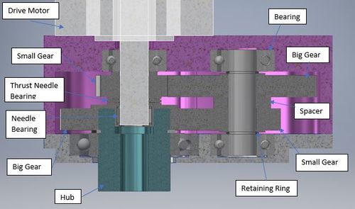
This gearbox is used with our drive motors in order to change the speed Mandiv is going vs if just the motor itself was used. This gearbox utilizes a reverse compound gear train and a hub to make the output and input shafts completely in line. The gears and hub are all constrained laterally by spacers and retaining rings. The drive motor is attached to the base of the gearbox (in pink) and the gearbox itself is attached to the top and bottom plates with screws.
Design Decisions
We decided to use a reverse compound gear train in order to make the overall size of the gearbox shorter.
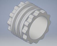
One of the biggest obstacles with designing a reverse compound gear train is dealing with the input and output shafts. This is because they are in live with each other, but spinning at different speeds. We decided to address this issue by making a hub for inside of the gearbox that would allow for a smooth transition from the input shaft to the output shaft without having to put a wall in between the two shafts. This decision was made instead of just simply adding a wall to separate the two shafts because adding a wall would mean the gearbox would have to get bigger than if we just made the hub. However, the hub will be harder to machine, so it's a trade-off.
We wanted to increase the overall drive speed of Mandiv, so we decided to use some bigger gears and up the gear ratio in order to make the robot faster than in previous years.
Calculations
The drive calcs sheet uses the drive motor specs (RPM), the robot weight, the wheel diameter, and the number of teeth on each gear in order to calculate the gear ratio and the output RPM from the gearbox. It then uses these values to calculate the max speed that the robot can drive at as well as its maximum pushing force. (Note: Remember there's a trade-off between torque and speed).
The gear stress calculator uses the gear specifications, the forces on each gear, and your desired safety margin in order to calculate the maximum stress on each gear that fits those specifications.
Differences from Mandiii
The gearbox Mandiii used was just a compound gear train whereas the one Mandiv is using is a reverse compound gear train. This decision was made because we wanted to decrease the overall footprint of the gearbox within the robot.
The gear sizes were changed in order to get a different gear ratio that would allow us to drive faster than Mandiii could (after comp with Mandiii, we felt that Mandiii was slower than other robots, so we wanted to make Mandiv be able to drive faster).
Notes/Helpful Reminders
The gears are constrained to the shafts via a key. This is crucial because without it the shaft and gear would spin independently.
The gearbox base (pink) and lid (grey) are made using the Haas and attached via the four screw holes shown on the lid.
All calculations for the gearbox can be found in the Mandiiii Dropbox in the design calculations excel file (drive calcs sheet) and the gear stress calculator excel sheet.
