Difference between revisions of "RoboCup: Kicker Board 2013"
(→Transformer Overview: removed inaccurate information) |
(→Kicker Charger: removed mention of discharge controller) |
||
| Line 11: | Line 11: | ||
[[File:Kicker charger.PNG|thumb|center|1200px]] | [[File:Kicker charger.PNG|thumb|center|1200px]] | ||
| − | This is the kicker board's charging circutry. This allows the board to charge large capacitors up to a very high voltage. This part of the board consists of | + | This is the kicker board's charging circutry. This allows the board to charge large capacitors up to a very high voltage. This part of the board consists of two main components: the bank capacitors and the flyback regulator. The bank capacitor is charged up to a high voltage and allows a high peak power delivery. The flyback controller is used to convert a low voltage, high current input to a high voltage, low current output. |
=== Flyback Converter === | === Flyback Converter === | ||
Revision as of 11:34, 3 March 2017
Contents
Overview
This is an overview of all the features and concepts on the 2013 kicker board made for the RoboCup competition by the electrical team of Georgia Institute of Technology's RoboCup team. This board's purpose is to drive a high voltage, high peak current solenoid to kick the ball. This page is to be used to farmiliarize new members of RoboCup with how the kicker board works.
Safety and Handling
This board uses high voltage. Be extremely careful around high voltage. It can cause considerable damage. Until you know that the capacitors are discharged, assume that they are still charged up to 250V. Check if there is a red LED lit on the back of the the kicker board. This is the death light. It is powered directly by the capacitors. If this light is on, you should not touch the board.
Kicker Charger
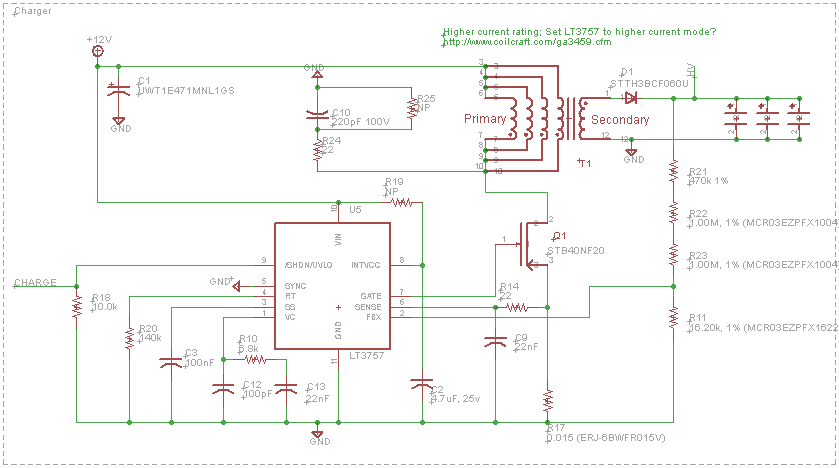
This is the kicker board's charging circutry. This allows the board to charge large capacitors up to a very high voltage. This part of the board consists of two main components: the bank capacitors and the flyback regulator. The bank capacitor is charged up to a high voltage and allows a high peak power delivery. The flyback controller is used to convert a low voltage, high current input to a high voltage, low current output.
Flyback Converter
The board currently uses a flyback [3] or buck-boost converter along with a transformer to create a very high voltage which we can store in the capacitors. A boost converter allows the output voltage to increase above what can be supplied as input. A very high voltage potential must be reached as soon as possible. This is done through a process of transferring potential energy.
First the supply voltage charges the transformer to some potential energy specified by the LT3757. The load loop is effectively locked in place by the potential of our capacitive load and a diode which prevents current from being discharged over the capacitors. The supply loop is then locked with a transistor by the LT3757. This forces all of the potential gathered in the transistor into the load loop. Not all of potential energy is transferred because there is already potential energy on the capacitors from the last round of charging. Once enough energy has been transferred to the capacitors the LT3757 will open up the supply loop. This restarts our process recharging the supply loop.
LT3757/Converter controller
The converter controller that is on the board is a LT3757 [4]. This chip manages the switching of our Buck-boost converter. When the supply loop has reached full capacity it will lock the supply loop. When the potential is transferred to the capacitors the supply loop is again unlocked. The LT3757 is an integrated circuit that uses inputs to determine precisely when to switch in order maximize power transfer. We can not do this manually or with our FPGA [5] and CPU [6] because of the asymptotic nature of capacitors and inductors. Unfortunately the LT3757 was designed for a resistive load, and while it can handle capacitive loads quite well there may be other chips that do it even better. We are looking at other possibilities and may improve on this component in the future.
Other converter methods
It has been suggested that other converter types may be able to charge the capacitors faster. A boost converter [7] may allow us to create a higher voltage potential. This would allow a faster transfer from the inductor to the capacitor. The other converter that has been looked at is the cuk converter [8]. A cuk converter might be able to allow the capacitors to be charged while other inductors are charging which would increase the rate of power transfer without raising the voltage across the capacitor. The electrical team is looking at these and other possibilities to improve on these systems in the future.
Voltage Monitor
This component is covered in detail on the control board page.
Kicker Trigger
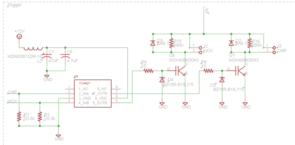
This section of the board allows the control board to release the energy stored in the capacitors into the kicker or chipper. This is done by using the TC4427 to control two high current, high voltage power transitors. These transistors will allow all of the energy stored in the capacitors to be released over the solenoid. There is a very value resistor and a diode pointing from the ground side of the solenoid to the power side in case the there is voltage overflow from the solenoid.
Auto-Discharge
The other way for the capacitors to discharge is the auto-discharger. This section is controled by either the control board, when it needs less voltage to kick with or the by the LT3757 when it has reached the maximum voltage allowed by the circutry. This discharger has much lower current transitors and large resistors that limit the discharge current. This is never used for discharging the capacitors fully as it will take longer than kicking and will release a lot of heat if the full capacitors were discharged over this section.
2008 Model of the 2013 Board
The 2013 kicker boards have redplaced out the previous models of the 2008 and 2011 boards. The 2013 board is based on the 2011 version with the addition of some updated parts and adding a voltage monitor for the capacitors. However, the 2008 board was very different. While the 2011 and 2013 kicker boards have a chip port, the 2008 boards and robots could not chip the ball. We have removed the chipping components from certain boards to avoid confusion with ports and plugs. Additionally, some of the 2008 model 2013 boards do not have voltage monitoring components because the control boards are unable to read the voltage monitor in 2008 mode
Parts list
Disclaimer: Some of the parts are not used in the final kicker board, but are printed on the mini board that is removed to make room for the capacitors. The parts list can be downloaded here.
References
- http://en.wikipedia.org/wiki/Transformer
- http://en.wikipedia.org/wiki/Inductor
- http://en.wikipedia.org/wiki/Flyback_converter
- http://cds.linear.com/docs/en/datasheet/3757Afd.pdf
- http://en.wikipedia.org/wiki/Field-programmable_gate_array
- http://en.wikipedia.org/wiki/Microprocessor
- http://en.wikipedia.org/wiki/Boost_converter
- http://en.wikipedia.org/wiki/%C4%86uk_converter

