Difference between revisions of "Data Acquisition"
AlexTheGreat (talk | contribs) |
Joldenburg6 (talk | contribs) m (Categorize) |
||
| (26 intermediate revisions by 5 users not shown) | |||
| Line 4: | Line 4: | ||
==Sensors== | ==Sensors== | ||
===[[GPS]]=== | ===[[GPS]]=== | ||
| + | ====Hardware==== | ||
| + | [[Image:Cf-md.jpg|right|thumb|A Hockey Puck]] | ||
For our first semester prototype, [[User:AlexTheGreat|Alex]] selected the: | For our first semester prototype, [[User:AlexTheGreat|Alex]] selected the: | ||
| − | [https://buy.garmin.com/shop/shop.do?cID=158&pID=8631 Garmin | + | [https://buy.garmin.com/shop/shop.do?cID=158&pID=8631 Garmin GPS 18 5Hz] ($200) |
*Updates every 200ms | *Updates every 200ms | ||
| Line 12: | Line 14: | ||
*Does not require a subscription to any service | *Does not require a subscription to any service | ||
*Voltage Requirement: 4.0-5.5V | *Voltage Requirement: 4.0-5.5V | ||
| + | |||
| + | ====Software==== | ||
| + | The GPS is attached to COM2 (RS232, /dev/ttyS1, 19200 8N1) on the TS-7800. | ||
| + | The GPS outputs a rising edge signal to allow precise time keeping, | ||
| + | gpsd interfaces with ntpd and reads the DCD line on COM2 to provide time information via network interface. | ||
| + | |||
| + | ====Status==== | ||
| + | gpsd trys to automatically determine the baud rate for serial communication, | ||
| + | needs to be recompiled so that the baud rate is fixed or a command line option. | ||
| + | ntpd should be trivial to have running as soon as gpsd is working reliably. | ||
| + | The default player NMEA driver may need to be modified to make use of the 5Hz update rate, | ||
| + | and to be aware of the precision time signal. | ||
| + | <br style="clear:both" /> | ||
===Gyro and Accelerometer=== | ===Gyro and Accelerometer=== | ||
| + | [[Image:Main-IMU-v3-0.jpg|thumb|right|150px|25¢]] | ||
The gyro and accelerometer are a combo system created by [http://www.sparkfun.com SparkFun]. It incorporates both the ADXL330 and IDG300 to enable measurements of acceleration along the x, y, and z axes and of angular rate about the x and y axes. For more information, please visit SparkFun's page on the IMU 5 Degrees of Freedom. | The gyro and accelerometer are a combo system created by [http://www.sparkfun.com SparkFun]. It incorporates both the ADXL330 and IDG300 to enable measurements of acceleration along the x, y, and z axes and of angular rate about the x and y axes. For more information, please visit SparkFun's page on the IMU 5 Degrees of Freedom. | ||
*[http://www.sparkfun.com/commerce/product_info.php?products_id=741 IMU 5 Degrees of Freedom] | *[http://www.sparkfun.com/commerce/product_info.php?products_id=741 IMU 5 Degrees of Freedom] | ||
*Voltage Requirement: 3.3V | *Voltage Requirement: 3.3V | ||
| + | <br style="clear:both" /> | ||
===Compass=== | ===Compass=== | ||
| − | *[http://www.sparkfun.com/commerce/product_info.php?products_id=236 Compass | + | [[Image:Main-PNI-V2Xe.jpg|thumb|Now in Green!]] |
| − | * | + | *[http://www.sparkfun.com/commerce/product_info.php?products_id=236 PNI Vector 2Xe Compass Module] |
| + | *SPI Interface | ||
| + | *Accuracy: Max: 2° RMS; Typical: 1° RMS | ||
| + | *Power Requirement: 2mA @ 3.3V | ||
| + | <br style="clear:both" /> | ||
===Wheel Encoders=== | ===Wheel Encoders=== | ||
| + | Current Wheel Encoders: [http://www.photocraftencoders.com/PDF_files/SR12%20SPEC.PDF SR12 Absolute Shaft Encoder] | ||
| + | |||
| + | We may be able to connect the encoder to the back of the motor instead of near the wheel. There is a recessed shaft (under a cover) at the back of the motor that is hexagonal (~0.79" diameter x ~0.17" long). As for mounting, there are four screw holes (size 8-32) equally spaced around the outside of the motor (~3.5" apart longways) and two recessed screw holes (size 8-32) inline with the outer holes (~2.7" apart longways). The inner holes don't have very much clearance to the motor wall near the outside (~0.15"). | ||
| + | <br style="clear:both" /> | ||
===Laser Range Finder=== | ===Laser Range Finder=== | ||
| Line 32: | Line 57: | ||
*Currently hoping to borrow one of these units from the Urban DARPA project | *Currently hoping to borrow one of these units from the Urban DARPA project | ||
*Outdoor model, used by all serious competitors | *Outdoor model, used by all serious competitors | ||
| + | <br style="clear:both" /> | ||
| + | |||
| + | |||
| + | |||
| + | |||
| + | |||
| + | ===Camera=== | ||
| + | Need to buy: | ||
| + | *AVT GUPPY F-036 COLOR CCD CAMERA [http://www.1stvision.com/cameras/AVT/avtg036.htm LINK] | ||
| + | * [http://www.goelectronic.com/Merchant2/merchant.mvc?Screen=PROD&Store_Code=GE&Product_Code=TAMRON+23FM65&Category_Code= wide angle 1/2" c mount lens] | ||
| + | |||
| + | [[Category: IGVC]][[Category:2008-2009]] | ||
Latest revision as of 21:35, 13 June 2018
Contents
Mission
Abstracting hardware sensors into quality data that can be accessed over a software interface
Sensors
GPS
Hardware
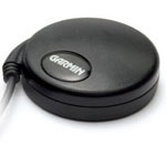
For our first semester prototype, Alex selected the: Garmin GPS 18 5Hz ($200)
- Updates every 200ms
- Accurate to at least 3.5m, expected accuracy of ~1m
- 12 parallel satellite tracking, WAAS enabled
- Does not require a subscription to any service
- Voltage Requirement: 4.0-5.5V
Software
The GPS is attached to COM2 (RS232, /dev/ttyS1, 19200 8N1) on the TS-7800. The GPS outputs a rising edge signal to allow precise time keeping, gpsd interfaces with ntpd and reads the DCD line on COM2 to provide time information via network interface.
Status
gpsd trys to automatically determine the baud rate for serial communication,
needs to be recompiled so that the baud rate is fixed or a command line option.
ntpd should be trivial to have running as soon as gpsd is working reliably.
The default player NMEA driver may need to be modified to make use of the 5Hz update rate,
and to be aware of the precision time signal.
Gyro and Accelerometer
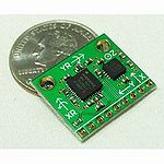
The gyro and accelerometer are a combo system created by SparkFun. It incorporates both the ADXL330 and IDG300 to enable measurements of acceleration along the x, y, and z axes and of angular rate about the x and y axes. For more information, please visit SparkFun's page on the IMU 5 Degrees of Freedom.
- IMU 5 Degrees of Freedom
- Voltage Requirement: 3.3V
Compass
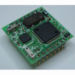
- PNI Vector 2Xe Compass Module
- SPI Interface
- Accuracy: Max: 2° RMS; Typical: 1° RMS
- Power Requirement: 2mA @ 3.3V
Wheel Encoders
Current Wheel Encoders: SR12 Absolute Shaft Encoder
We may be able to connect the encoder to the back of the motor instead of near the wheel. There is a recessed shaft (under a cover) at the back of the motor that is hexagonal (~0.79" diameter x ~0.17" long). As for mounting, there are four screw holes (size 8-32) equally spaced around the outside of the motor (~3.5" apart longways) and two recessed screw holes (size 8-32) inline with the outer holes (~2.7" apart longways). The inner holes don't have very much clearance to the motor wall near the outside (~0.15").
Laser Range Finder
Current LIDAR: Hokuyo URG-04LX
- Indoor model, not suitable to our needs
Next Semester LIDAR: SICK LMS
- Currently hoping to borrow one of these units from the Urban DARPA project
- Outdoor model, used by all serious competitors
Camera
Need to buy:
- AVT GUPPY F-036 COLOR CCD CAMERA LINK
- wide angle 1/2" c mount lens


