Difference between revisions of "How to Guide Inventor"
(→Setting Up Inventor) |
Athrasher7 (talk | contribs) m |
||
| (52 intermediate revisions by 8 users not shown) | |||
| Line 1: | Line 1: | ||
| − | [http://en.wikipedia.org/wiki/Autodesk_Inventor Inventor], produced by [http://www.autodesk.com Autodesk], is the | + | [[Category: How to Guides: Technical]] |
| + | |||
| + | [http://en.wikipedia.org/wiki/Autodesk_Inventor Inventor], produced by [http://www.autodesk.com Autodesk], is the 3D solid modeling software currently used by the RoboJackets. The software can be downloaded for free at [http://students.autodesk.com http://students.autodesk.com] (you need a valid email address from a college ie. your @gatech.edu address). This guide is based off of Inventor 2008 and 2009. Inventor 2010 still works the same and has the shortcut keys, but has a ribbon style GUI. | ||
| + | |||
| + | Autodesk has released a set of [http://help.autodesk.com/view/INVNTOR/2014/ENU/?guid=GUID-A8795BBB-D723-444D-B36F-81573A6E1022 Essential Skills Videos] that is a great place to start learning. | ||
==Setting Up Inventor== | ==Setting Up Inventor== | ||
| − | In order to do anything you need to setup your project file. By creating this you can more easily keep track of just project X or project Y and have them on the same machine. | + | In order to do anything, you need to setup your project file. By creating this you can more easily keep track of just project X or project Y and have them on the same machine. |
To Do This: | To Do This: | ||
| Line 10: | Line 14: | ||
# Fill in the requested info | # Fill in the requested info | ||
Note: There are many ways to get to the projects window. | Note: There are many ways to get to the projects window. | ||
| + | |||
| + | Now you will have you new project listed in the project window. However when you start inventor you will not by default be working in it. To make this the default project just double click on your project in the list. Now when you start you will always be working with it. | ||
==Making a Part== | ==Making a Part== | ||
| − | First we need to create a part file. To do this. | + | First we need to create a part file. To do this File > New > Select Standard.ipt |
| + | |||
===Making a Sketch=== | ===Making a Sketch=== | ||
| − | Like AutoCAD (also made by Autodesk) Inventor has many shortcut keys (some of them are the same). | + | [[Image:Inv_sketch_start.jpg|thumb|left|Starting out a sketch]] |
| + | Like AutoCAD (also made by Autodesk) Inventor has many shortcut keys (some of them are the same). To your left you will see two panels. On the top you have Model and on the bottom you have 2D Sketch. The bottom panel will change depending on what you are doing (Note: these are the default locations and these windows are movable). You will also notice beside each title there is a drop down arrow these provide more features which you can explore. Though generally you will not use these additional features. | ||
| + | |||
| + | Generally (by default) the top panel will house info about the current file you are in and the bottom panel will hold commands that you can use to create your product. | ||
| + | <br clear="all" /> | ||
====Lines==== | ====Lines==== | ||
| − | To do a line you can hit | + | To do a line you can hit L and then click around to draw what you need to. To stop drawing lines (along with any other command) hit Esc. By default lines will attempt to orient them selves parallel and perpendicular with other lines. |
====Circles==== | ====Circles==== | ||
| − | There is more than one way to make a circle. To specify a | + | There is more than one way to make a circle. By default and when you hit C it will make one from the center of the point that you select. To change this click the down arrow beside the circle button. |
| + | |||
| + | ====More==== | ||
| + | You can also create boxes. More importantly there is a trim command short cut X. With trim you could draw a triangle and place a circle on the end of it. Then remove only the lines that you want and end up with an ice cream cone. | ||
| + | |||
| + | Project Geometry is is by far one of the most useful tools (later on once you have more than one file). With this you can bring forward outlines from other parts or features on the same part and create sketches that a driven off of something else. These sketches will automatically update when that something else is changed. | ||
| + | |||
| + | ====Dimensioning==== | ||
| + | Before we go any further we need to fully dimension our sketch. This keeps it from changing and locks it in place. As of now all of our lines will be green and once we are done they will be black. To get started hit D. (Note: You can auto dimension the sketch however sometimes it is better to manually do it. You may want your sketch to be based off of direction X or Y and keep this or that side more readily adjustable.) You may need to specify its distance from the origin. To do this make the axises visible and project their geometry. | ||
| + | |||
| + | Once you have created a dimension you can edit it by click on it (it will go from black to red while hovering). You can input any formula you want. | ||
| + | |||
| + | A dimension can also be based of off of other dimensions. To do this simply create a dimension like you would normally and edit it. Once the window is up for you to key in a formula or number click on the dimension(s) you want it to be based off of. You can then manipulate them as if they were variables in an equation (which they are). | ||
| + | |||
| + | ===Make Features=== | ||
| + | In order to make your 2-dimensional sketch into something more tangible you will need to utilize various features depending on your situation. Overtime you will figure out what your situation is and what to do. | ||
| + | |||
| + | ====Extrude==== | ||
| + | [[Image:Inv_extrude_win.jpg|thumb|right|Normal Extrusion Window in Inventor]] | ||
| + | This makes a perpendicular projection of set length from a selected profile (sketch). To do this hit E. A window will appear with options on how to preform the extrusion. | ||
| + | |||
| + | To preform a Normal Extrusion: | ||
| + | # Hit E | ||
| + | # Select profile or sketch | ||
| + | # Key in distance | ||
| + | # Select direction (Forward, Backward, or 1/2 forward & 1/2 backward) | ||
| + | <br clear="all" /> | ||
| + | ====Revolve==== | ||
| + | [[Image:Inv_rev_win.jpg|thumb|right|Revolve Extrusion Window]] | ||
| + | Produces a rotation of X degrees around a specified axis. You can added a line to your sketch and use it as that rotation axis or use an edge of the sketch. | ||
| + | |||
| + | To preform an Revolved Extrusion: | ||
| + | # Hit R | ||
| + | # Select the profile or sketch | ||
| + | # Select axis of rotation | ||
| + | # Specify extent (Full = 360, To = To a face, To From = From one location to another location, Angel = Specify degree) | ||
| + | <br clear="all" /> | ||
| + | ====Sweep==== | ||
| + | ====Loft==== | ||
| − | === | + | ====Hole==== |
| − | + | When making holes for a bolted connection, it is better to use the hole tool instead of drawing them into your sketch initially and extruding or doing a cut. | |
| − | + | Benefits of using the hole tool include: | |
| + | * standard hole sizes for bolts | ||
| + | * thread and depth | ||
| + | * finishing options (counter sink, counter bore, etc.) | ||
| + | * easy adjustment of parameters | ||
| − | + | Other types of holes may be generated using the [[#Normal|extrude]] tool. | |
| − | ==== | + | ====Fillet==== |
| − | === | + | ====Chamfer==== |
| − | |||
| − | == | + | ===Properties=== |
| + | [[Image:Inv_iprop_win.jpg|thumb|right|iProperties Window in Inventor]] | ||
| + | Now that you part is complete you are not done! Go to File > iProperties > Physical Tab | ||
| + | |||
| + | Set your material type and hit update. Then apply and close the window. Doing this allows inventor to: a) give you and estimated weight of your robot and b) give you a estimated cg location. Note: If you have a part like fan or an entire assembly like a motor you can weight the thing and then manually key in its mass on that window. | ||
| + | |||
| + | <br clear="all" /> | ||
| + | |||
| + | ==Assembling Parts== | ||
Now that you have your parts lets put them together to make some sort of subsystem, product, etc. To do this you will need to create an assembly. Note: Assemblies can be composed of parts and other assemblies. | Now that you have your parts lets put them together to make some sort of subsystem, product, etc. To do this you will need to create an assembly. Note: Assemblies can be composed of parts and other assemblies. | ||
| Line 42: | Line 102: | ||
#### Gears (Parts) | #### Gears (Parts) | ||
#### Plates (Parts) | #### Plates (Parts) | ||
| − | #### Shaft ( | + | #### Shaft (Part) |
## Frame Assem | ## Frame Assem | ||
### Tubes / Angle (parts) | ### Tubes / Angle (parts) | ||
| Line 49: | Line 109: | ||
## Bumpers | ## Bumpers | ||
| + | [[Image:Inv_assembly_win.jpg|thumb|right|Constraint dialog in Inventor]] | ||
===Constraints=== | ===Constraints=== | ||
| − | ==Making | + | Constraints, like in the sketching phase, are used in assembly phase to align parts in the fashion it will resemble in real life. First components must be placed, with the first component as grounded. Then the constraints dialog can be pulled up by hitting the key. |
| − | ===Drawing Files=== | + | |
| + | The first tab deals with assembly constraints and it is what we will be working with here. The options here are mate, angle, tangent and insert. They respectively align faces, corners, circular objects and cylinders to other faces, corners, surfaces and holes. | ||
| + | |||
| + | === Mate === | ||
| + | |||
| + | [[File:Inv assembly 4.jpg|thumb|left|text-top|upright|Flush with a .2 in offset]] [[File:Inv assembly 2.jpg|thumb|right|text-top|upright|Mate]] Mate is the first option and it comes in two modes, flush and mate. Two surfaces are selected and then they are stuck next to each other when using mate. | ||
| + | |||
| + | Flush (seen left) on the other aligns surfaces or planes with each other. A typical set of constraints use a single mate and two flushes to firmly stick two components to each other in a rigid orientation (three dimensions of movement requires three constraints). Offsets can also be described for additional flexibility in binding components together. | ||
| + | |||
| + | === === | ||
| + | |||
| + | === === | ||
| + | |||
| + | === Insert === | ||
| + | |||
| + | [[File:Inv assembly 5.jpg|thumb|left|text-top|upright|Axial arrows on circular faces when selecting surfaces for insertion]] [[File:Inv assembly 6.jpg|thumb|right|text-top|upright|Axes are aligned in the same direction]] Insert typically inserts a cylindrical object into a hole. The first two selections of the participating circular faces also show an axial arrow. | ||
| + | |||
| + | There is an option to have the arrows oppose each other or point in the same direction. This gives two different types of inserts, so choose the circular face correctly may save time and additional constraints. | ||
| + | |||
| + | Insert constraints have variable offsets as well, and if no offset is specified, then the components are free to slide along the highlighted axis of insertion. | ||
| + | |||
| + | |||
| + | |||
| + | |||
| + | |||
| + | --- | ||
| + | |||
| + | == Making your Parts and Assemblies Useful == | ||
| + | |||
| + | === Drawing Files === | ||
| + | |||
| + | '''Drawing files''' (.dwg) in Inventor are essentially 2D schematics of your parts and assemblies, which can be used for presentations, machining guides, and as fleshed out design documents. We also use drawings as the 2D input for the waterjet. | ||
| + | |||
| + | To add contents to a drawing file, first import the "base view" of each .ipt file for the parts you want to add (right click, then select "base view", then select your file). Then choose a 2D perspective of the part to display in the schematic. Some of these perspectives include: Top, Left, Right, Back, and Bottom. For''3D designs'', you will usually show 3 perspectives, the top, the broad side, and the short side (x, y, and z, essentially). Any unique part of a component or set of components should be highlighted from its most descriptive angle. It is essential that the drawings give anyone with the schematic enough information to understand and/or physically create the the full part or set of parts. Essential information may include: a bill of materials, material types, special notes, cut-outs and insets ("details"), and most importantly, your parts' dimensions'''.''' | ||
| − | ==== | + | === Dimensioning === |
| + | |||
| + | <span style="line-height: 20.8px;">The most important information you can include in a drawing file is its dimensioning. This is essential for understanding and crafting the parts in your drawing in the real world. You can annotate most of this information using the Dimension tool, under the "Annotate" section.</span> | ||
| + | |||
| + | <span style="line-height: 20.8px;">Required dimensioning includes:</span> | ||
| + | |||
| + | *<span style="line-height: 20.8px;">the length, width, and height (thickness) of all components</span> | ||
| + | *<span style="line-height: 20.8px;">the radius of all holes </span> | ||
| + | *<span style="line-height: 20.8px;">relative locations of all holes or cuts </span> | ||
| + | **e.g. <span style="line-height: 20.8px;">radius from center, distance from edge</span> | ||
| + | *<span style="line-height: 20.8px;">fillet, chamfer, polygon, and extrude angles</span> | ||
| + | *<span style="line-height: 20.8px;">any pattern details</span> | ||
| + | **<span style="line-height: 20.8px;">e.g. 5 holes over a distance of 5.5 inches</span> | ||
| + | |||
| + | ==Appendix== | ||
| + | ===Useful Short Cut Keys=== | ||
| + | * Inventor Wide | ||
| + | ** Zoom to fit = Home | ||
| + | ** Look at face = Page Up | ||
| + | ** Ending a command = Esc | ||
| + | ** Pan = F2 (Hold) | ||
| + | ** Zoom = F3 (Hold) | ||
| + | ** Rotate = F4 (Hold) | ||
| + | ** Cycle Through Views = F5 | ||
| + | ** Isometric View = F6 | ||
| + | * Parts | ||
| + | ** 2D Sketches | ||
| + | *** Line = L | ||
| + | *** Circle = C | ||
| + | *** Trim = X | ||
| + | *** Dimension = D | ||
| + | ** Modeling | ||
| + | *** Extrude = E | ||
| + | *** Revolve = R | ||
| + | *** Fillet = F | ||
| + | *** Mirror = Ctrl + Shift + M | ||
| + | *** Circular Pattern = Ctrl + Shift + C | ||
| + | *** Rectangular Pattern = Ctrl + Shift + R | ||
| + | *** Loft = Ctrl + Shift + L | ||
| + | *** Sweep = Ctrl + Shift + S | ||
| + | * Assemblies | ||
| + | * Drawings | ||
| + | |||
| + | ===Mouse Use=== | ||
| + | * Pan = Center Click | ||
| + | * Zoom in / out = Scroll up / down | ||
| + | |||
| + | ===Changing Units=== | ||
| + | * When entering a dimension, simply type in the abbreviation for the unit. Inventor will convert automatically. | ||
| + | * To change the entire part, click Tools>Document Settings. On the Units tab, select your new units appropriately. | ||
| − | [[ | + | ===Resources=== |
| + | *[http://help.autodesk.com/view/INVNTOR/2014/ENU/?guid=GUID-A8795BBB-D723-444D-B36F-81573A6E1022 Essential Skills Videos] | ||
| + | *[http://help.autodesk.com/view/INVNTOR/2014/ENU/ Autodesk Inventor WikiHelp] | ||
| + | *[http://www.cadsetterout.com/inventor-tutorials/101-autodesk-inventor-productivity-tips/ Productivity Tips] | ||
Latest revision as of 21:00, 5 February 2020
Inventor, produced by Autodesk, is the 3D solid modeling software currently used by the RoboJackets. The software can be downloaded for free at http://students.autodesk.com (you need a valid email address from a college ie. your @gatech.edu address). This guide is based off of Inventor 2008 and 2009. Inventor 2010 still works the same and has the shortcut keys, but has a ribbon style GUI.
Autodesk has released a set of Essential Skills Videos that is a great place to start learning.
Contents
Setting Up Inventor
In order to do anything, you need to setup your project file. By creating this you can more easily keep track of just project X or project Y and have them on the same machine.
To Do This:
- Go to File
- Projects
- Click the new button
- Fill in the requested info
Note: There are many ways to get to the projects window.
Now you will have you new project listed in the project window. However when you start inventor you will not by default be working in it. To make this the default project just double click on your project in the list. Now when you start you will always be working with it.
Making a Part
First we need to create a part file. To do this File > New > Select Standard.ipt
Making a Sketch
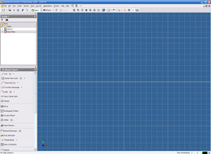
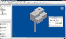
Like AutoCAD (also made by Autodesk) Inventor has many shortcut keys (some of them are the same). To your left you will see two panels. On the top you have Model and on the bottom you have 2D Sketch. The bottom panel will change depending on what you are doing (Note: these are the default locations and these windows are movable). You will also notice beside each title there is a drop down arrow these provide more features which you can explore. Though generally you will not use these additional features.
Generally (by default) the top panel will house info about the current file you are in and the bottom panel will hold commands that you can use to create your product.
Lines
To do a line you can hit L and then click around to draw what you need to. To stop drawing lines (along with any other command) hit Esc. By default lines will attempt to orient them selves parallel and perpendicular with other lines.
Circles
There is more than one way to make a circle. By default and when you hit C it will make one from the center of the point that you select. To change this click the down arrow beside the circle button.
More
You can also create boxes. More importantly there is a trim command short cut X. With trim you could draw a triangle and place a circle on the end of it. Then remove only the lines that you want and end up with an ice cream cone.
Project Geometry is is by far one of the most useful tools (later on once you have more than one file). With this you can bring forward outlines from other parts or features on the same part and create sketches that a driven off of something else. These sketches will automatically update when that something else is changed.
Dimensioning
Before we go any further we need to fully dimension our sketch. This keeps it from changing and locks it in place. As of now all of our lines will be green and once we are done they will be black. To get started hit D. (Note: You can auto dimension the sketch however sometimes it is better to manually do it. You may want your sketch to be based off of direction X or Y and keep this or that side more readily adjustable.) You may need to specify its distance from the origin. To do this make the axises visible and project their geometry.
Once you have created a dimension you can edit it by click on it (it will go from black to red while hovering). You can input any formula you want.
A dimension can also be based of off of other dimensions. To do this simply create a dimension like you would normally and edit it. Once the window is up for you to key in a formula or number click on the dimension(s) you want it to be based off of. You can then manipulate them as if they were variables in an equation (which they are).
Make Features
In order to make your 2-dimensional sketch into something more tangible you will need to utilize various features depending on your situation. Overtime you will figure out what your situation is and what to do.
Extrude
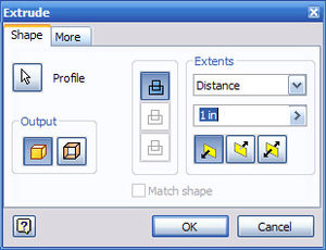
This makes a perpendicular projection of set length from a selected profile (sketch). To do this hit E. A window will appear with options on how to preform the extrusion.
To preform a Normal Extrusion:
- Hit E
- Select profile or sketch
- Key in distance
- Select direction (Forward, Backward, or 1/2 forward & 1/2 backward)
Revolve
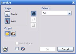
Produces a rotation of X degrees around a specified axis. You can added a line to your sketch and use it as that rotation axis or use an edge of the sketch.
To preform an Revolved Extrusion:
- Hit R
- Select the profile or sketch
- Select axis of rotation
- Specify extent (Full = 360, To = To a face, To From = From one location to another location, Angel = Specify degree)
Sweep
Loft
Hole
When making holes for a bolted connection, it is better to use the hole tool instead of drawing them into your sketch initially and extruding or doing a cut. Benefits of using the hole tool include:
- standard hole sizes for bolts
- thread and depth
- finishing options (counter sink, counter bore, etc.)
- easy adjustment of parameters
Other types of holes may be generated using the extrude tool.
Fillet
Chamfer
Properties
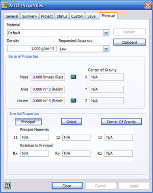
Now that you part is complete you are not done! Go to File > iProperties > Physical Tab
Set your material type and hit update. Then apply and close the window. Doing this allows inventor to: a) give you and estimated weight of your robot and b) give you a estimated cg location. Note: If you have a part like fan or an entire assembly like a motor you can weight the thing and then manually key in its mass on that window.
Assembling Parts
Now that you have your parts lets put them together to make some sort of subsystem, product, etc. To do this you will need to create an assembly. Note: Assemblies can be composed of parts and other assemblies.
Ideally your robot's assembly structure could look like this:
- Main Robot Assem
- Drive Train Assem
- Gearbox Assem
- Gears (Parts)
- Plates (Parts)
- Shaft (Part)
- Gearbox Assem
- Frame Assem
- Tubes / Angle (parts)
- Bolts (parts)
- Manipulators
- Bumpers
- Drive Train Assem
Constraints
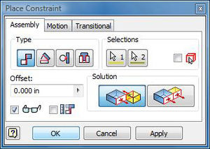
Constraints, like in the sketching phase, are used in assembly phase to align parts in the fashion it will resemble in real life. First components must be placed, with the first component as grounded. Then the constraints dialog can be pulled up by hitting the key.
The first tab deals with assembly constraints and it is what we will be working with here. The options here are mate, angle, tangent and insert. They respectively align faces, corners, circular objects and cylinders to other faces, corners, surfaces and holes.
Mate
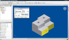
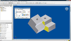
Mate is the first option and it comes in two modes, flush and mate. Two surfaces are selected and then they are stuck next to each other when using mate.
Flush (seen left) on the other aligns surfaces or planes with each other. A typical set of constraints use a single mate and two flushes to firmly stick two components to each other in a rigid orientation (three dimensions of movement requires three constraints). Offsets can also be described for additional flexibility in binding components together.
Insert
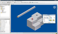
Insert typically inserts a cylindrical object into a hole. The first two selections of the participating circular faces also show an axial arrow.
There is an option to have the arrows oppose each other or point in the same direction. This gives two different types of inserts, so choose the circular face correctly may save time and additional constraints.
Insert constraints have variable offsets as well, and if no offset is specified, then the components are free to slide along the highlighted axis of insertion.
---
Making your Parts and Assemblies Useful
Drawing Files
Drawing files (.dwg) in Inventor are essentially 2D schematics of your parts and assemblies, which can be used for presentations, machining guides, and as fleshed out design documents. We also use drawings as the 2D input for the waterjet.
To add contents to a drawing file, first import the "base view" of each .ipt file for the parts you want to add (right click, then select "base view", then select your file). Then choose a 2D perspective of the part to display in the schematic. Some of these perspectives include: Top, Left, Right, Back, and Bottom. For3D designs, you will usually show 3 perspectives, the top, the broad side, and the short side (x, y, and z, essentially). Any unique part of a component or set of components should be highlighted from its most descriptive angle. It is essential that the drawings give anyone with the schematic enough information to understand and/or physically create the the full part or set of parts. Essential information may include: a bill of materials, material types, special notes, cut-outs and insets ("details"), and most importantly, your parts' dimensions.
Dimensioning
The most important information you can include in a drawing file is its dimensioning. This is essential for understanding and crafting the parts in your drawing in the real world. You can annotate most of this information using the Dimension tool, under the "Annotate" section.
Required dimensioning includes:
- the length, width, and height (thickness) of all components
- the radius of all holes
- relative locations of all holes or cuts
- e.g. radius from center, distance from edge
- fillet, chamfer, polygon, and extrude angles
- any pattern details
- e.g. 5 holes over a distance of 5.5 inches
Appendix
Useful Short Cut Keys
- Inventor Wide
- Zoom to fit = Home
- Look at face = Page Up
- Ending a command = Esc
- Pan = F2 (Hold)
- Zoom = F3 (Hold)
- Rotate = F4 (Hold)
- Cycle Through Views = F5
- Isometric View = F6
- Parts
- 2D Sketches
- Line = L
- Circle = C
- Trim = X
- Dimension = D
- Modeling
- Extrude = E
- Revolve = R
- Fillet = F
- Mirror = Ctrl + Shift + M
- Circular Pattern = Ctrl + Shift + C
- Rectangular Pattern = Ctrl + Shift + R
- Loft = Ctrl + Shift + L
- Sweep = Ctrl + Shift + S
- 2D Sketches
- Assemblies
- Drawings
Mouse Use
- Pan = Center Click
- Zoom in / out = Scroll up / down
Changing Units
- When entering a dimension, simply type in the abbreviation for the unit. Inventor will convert automatically.
- To change the entire part, click Tools>Document Settings. On the Units tab, select your new units appropriately.
